
997C SI COMBO - GPS Fishfinder HUMMINBIRD - Free user manual and instructions
Find the device manual for free 997C SI COMBO HUMMINBIRD in PDF.

User questions about 997C SI COMBO HUMMINBIRD
0 question about this device. Answer the ones you know or ask your own.
Ask a new question about this device
Download the instructions for your GPS Fishfinder in PDF format for free! Find your manual 997C SI COMBO - HUMMINBIRD and take your electronic device back in hand. On this page are published all the documents necessary for the use of your device. 997C SI COMBO by HUMMINBIRD.
USER MANUAL 997C SI COMBO HUMMINBIRD
Installation and Operations Manual
997c SI Combo
Thank You!
Thank you for choosing Humminbird®, America's #1 name in fishfinders. Humminbird® has built its reputation by designing and manufacturing top-quality, thoroughly reliable marine equipment. Your Humminbird® is designed for trouble-free use in even the harshest marine environment. In the unlikely event that your Humminbird® does require repairs, we offer an exclusive Service Policy - free of charge during the first year after purchase, and available at a reasonable rate after the one-year period. For complete details, see the Warranty section in this manual. We encourage you to read this installation and operations manual carefully in order to get full benefit from all the features and applications of your Humminbird® product.
Contact our Customer Resource Center at either 1-800-633-1468 or visit our website at www.humminbird.com.
WARNING! This device should not be used as a navigational aid to prevent collision, grounding, boat damage, or personal injury. When the boat is moving, water depth may change too quickly to allow time for you to react. Always operate the boat at very slow speeds if you suspect shallow water or submerged objects.
WARNING! Disassembly and repair of this electronic unit should only be performed by authorized service personnel. Any modification of the serial number or attempt to repair the original equipment or accessories by unauthorized individuals will void the warranty. Handling and/or opening this unit may result in exposure to lead, in the form of solder.
WARNING! This product contains lead, a chemical known to the state of California to cause cancer, birth defects and other reproductive harm.
NOTE: Some features discussed in this manual require a separate purchase, and some features are only available on international models. Every effort has been made to clearly identify those features. Please read the manual carefully in order to understand the full capabilities of your model.
900 Series™, Cannon™, CannonLink™, DualBeam PLUST™, Fish ID+™, HumminbirdPCTM, Humminbird®, InterLink™, One-Touch® Zoom, QuadraBeam PLUST™, RTSS® Window, SmartCast®, Structure ID®, Total Screen Update®, TrueArch®, WeatherSense®, WhiteLine®, WideSide®, X-Press™, and X-Press™ Menu are trademarked by or registered trademarks of Humminbird®.
© 2007 Humminbird®, Eufaula AL, USA. All rights reserved.
Table of Contents
900 SeriesTM Introduction 1
How the 900 Series™ Works 1
High Definition Side Imaging Sonar 2
QuadraBeam PLUS™ Sonar (optional-purchase QuadraBeam PLUS™ transducer only) 3
Universal Sonar 2 4
How GPS and Cartography Work 4
Multi-Media Card (MMC)/SD Slot 5
Software Updates 5
Accessory Bus 6
Installation Overview 6
Control Head Installation 7
Gimbal Mounting the Control Head 7
Connecting the Control Head Power Cable to the Boat 12
Transducer Installation 13
Transom Transducer Installation 14
Trolling Motor Transducer Installation 19
Trolling Motor Transducer Options 19
Test and Finish the Transducer Installation 20
GPS Receiver Installation 21
Stem Mounting with an Existing 1" - 14 Thread Stem 21
Access Under Mounting Location 22
No Access Under Mounting Location 23
Finish Routing the Cable and Check GPS Receiver Operation 23
Testing the System Installation 24
Getting Started - Using Your 900 SeriesTM 25
Powering Up the Control Head 25
What's on the Sonar Display 26
Understanding Sonar History 27
Real Time Sonar (RTS®) Window 27
Sonar Bottom Presentation 28
Understanding Side Imaging 29
What's on the Side Imaging Display 30
Side Imaging Technology: How It Works 31
Side Imaging: On the Water Interpretation 31
Key Functions 34
POWER/LIGHT Key 34
VIEWKey 35
35
4-WAY Cursor Control Key 36
View Preset Keys 36
EXITKey 36
INFO Key 37
MARK Key 37
GOTO Key 37
Z00M (+ / - ) Keys 38
Table of Contents
Views 38
Views and Readouts 39
Side Imaging View 39
Sonar View 40
Sonar Zoom View 41
Split Sonar View 42
Side/Sonar Combo View 43
Snapshot and Recording View 43
Side Beam View (with optional-purchase QuadraBeam PLUS™ transducer only) 48
Bird's Eye View 50
Chart/Bird's Eye Combo View 51
Chart/Chart Combo View 52
Chart View 53
Chart/Sonar Combo View. 54
Chart/SideComboView 55
Chart Orientation 56
Viewing Cartography 56
Navigation 57
Waypoints, Routes and Tracks. 58
Save, Edit, or Delete a Waypoint 59
Navigate to a Waypoint or Position 60
Add a Waypoint Target or Trolling Grid 60
Save, Edit or Delete a Route 61
Save or Clear a Current Track 62
Edit,Delete or Hide Saved Tracks 62
Man Overboard (MOB) Navigation 63
The Menu System 64
Start-Up Options Menu 65
Normal Operation 66
Simulator 66
System Status 66
Self Test 67
Accessory Test. 67
GPS Diagnostic View 68
Sonar X-PressTM Menu 69
Active Side 69
Split Position 70
Sensitivity 70
Upper Range (Advanced: Sonar, Split Sonar and Active Sonar Side Views only) 71
Lower Range 71
Chart Speed 72
Quad Layout (with optional-purchase QuadraBeam PLUS™ Transducer, Side Beam View only) 72
Bottom Lock (Sonar Zoom View only) 73
Bottom Range (Sonar Zoom View only, when Bottom Lock is on) 73
Sonar Colors 73
Cancel Navigation (only when navigating) 73
Table of Contents
Side Imaging X-PressTM Menu 74
Active Side 74
Split Position 74
SI Side 75
SI Sensitivity 75
SI Range 75
Chart Speed 75
SI Colors. 76
Navigation X-PressTM Menu 76
Active Side. 77
Split Position 77
Waypoint [Name] (only with an active cursor on a waypoint) 77
Cursor to Waypoint (Chart or Combo view only) 78
Save Current Track 78
Clear Current Track 78
Save Current Route (only when navigating) 79
Skip Next Waypoint (only when navigating) 79
Cancel Navigation (only when navigating) 79
Cancel MOB Navigation (only when MOB Navigation is activated) 79
Remove Target (only if a Target is active) 80
Remove Grid (only if a Grid is active) 80
Waypoint Name (most recently-created waypoint) 80
Snapshot and Recording X-PressTM Menu (Snapshot and Recording View only) 81
Start Recording (optional-purchase MMC/SD Card, Snapshot and Recording View only) 82
Stop Recording (optional-purchase MMC/SD Card only) 82
Delete Image (optional-purchase MMC/SD Card, Snapshot and Recording View only) 82
Delete All Images (optional-purchase MMC/SD Card, Snapshot and Recording View only) 83
Delete Recording (optional-purchase MMC/SD Card, Snapshot and Recording View only) 83
Delete All Recordings (optional-purchase MMC/SD Card, Snapshot and Recording View only) 84
Pings Per Second (optional-purchase MMC/SD Card, Snapshot and Recording View only) 84
Playback Speed (optional-purchase MMC/SD Card, Snapshot and Recording View only) 84
StopPlayback(optional-purchaseMMC/SDCardonly) 85
Sonar Menu Tab 85
Beam Select 86
Side View Frequency (Side Views only) 86
Zoom Width (Sonar Zoom View only) 89
83 kHz Sensitivity 89
Table of Contents
455 kHz Sensitivity (Advanced, with optional-purchase QuadraBeam PLUS™ transducer only) ..... 89
Depth Lines (Advanced) 90
Surface Clutter (Advanced) 91
Noise Filter (Advanced) 91
Max Depth (Advanced) 92
Water Type (Advanced) 92
Transducer Select 93
Color Bar 93
Temperature Graph (Sonar View only, with Temperature input) 93
Navigation Menu Tab 94
Current Track 94
Saved Tracks 95
Waypoints 95
Routes 96
Chart Orientation 96
North Reference 97
Trolling Grid Rotation 97
Trackpoint Interval 97
Track Min Distance (Advanced) 98
Track Color Range 98
Map Datum (Advanced) 98
Course Projection Line 99
Export All Nav Data (Advanced) 99
Delete All Nav Data (Advanced) 99
Continuous Navigation Mode 99
Chart Menu Tab 100
Chart Detail Level 100
Map Borders 101
Lat/Lon Grid. 101
Spot Soundings 101
Navaids on Bird's Eye View 102
Shaded Depth 102
Set Simulation Position (Advanced) 102
Set Map Offset (Advanced) 103
Clear Map Offset (Advanced) 103
Alarms Menu Tab 104
Depth Alarm 104
Fish ID Alarm 104
Low Battery Alarm 105
Aux Temp Alarm (with optional-purchase temp. probe or Temp/Speed only) 105
Temp Alarm 106
Off Course Alarm 106
Arrival Alarm 107
Drift Alarm 107
Alarm Tone 108
Setup Menu Tab 108
Units - Depth 109
Units - Temp (International only) 109
Units - Distance (with Speed input only) 109
Table of Contents
Units - Speed (with Speed input only) 109
User Mode. 110
Language (International only) 110
Triplog Reset (with Speed input only) 110
Temp Offset (Advanced) 113
Speed Calibration (Advanced, with Speed paddle wheel only) 113
Local Time Zone (Advanced) 113
Daylight Saving Time (Advanced) 114
Position Format (Advanced) 114
Time Format (Advanced, International only) 114
Date Format (Advanced, International only) 114
Digits Format (Advanced) 115
NMEA Output (Advanced) 115
Sonar 116
Views Menu Tab 116
Accessories Menu Tab 118
Using Screen Snapshot 118
Troubleshooting 120
900 SeriesTM Doesn't Power Up 120
900 Series™ Defaults to Simulator with a Transducer Attached 120
Display Problems 121
Finding the Cause of Noise 122
1-Year Limited Warranty 123
Humminbird® Service Policy 123
900 Series™ Accessories 125
Specifications 127
Glossary 128
Appendix A - Transducer Mounting Template: XHS 9 HDSI 180 T 138
Contact Humminbird 139
NOTE: Entries in this Table of Contents which list (International only) are only available on products sold outside of the US and Canada by our authorized International Distributors. To obtain a list of authorized International Distributors, please visit our website at www.humminbird.com or contact our Customer Resource Center at 1-800-633-1468 to locate the distributor nearest you.
NOTE: Entries in this Table of Contents which list (with Speed Input) or (with Temperature Input) may require the purchase of separate accessories. You can visit our website at www.humminbird.com to order these accessories online or contact our Customer Resource Center at 1-800-633-1468.
900 Series™ Introduction
Your 900 Series™ Ultra Wide Screen Fishing System comes in the following configuration:
- Humminbird® 997c Combo: Ultra Wide Screen Fishing System with Chartplotter (Maps) and Side Imaging and Dual Frequency Transducer, GPS Receiver included.
How Sonar Works
Sonar technology is based on sound waves. The 900 Series™ Fishing System uses sonar to locate and define structure, bottom contour and composition, as well as depth directly below the transducer.
Your 900 Series™ Fishing System sends a sound wave signal and determines distance by measuring the time between the transmission of the sound wave and when the sound wave is reflected off of an object; it then uses the reflected signal to interpret location, size, and composition of an object.
Sonar is very fast. A sound wave can travel from the surface to a depth of 240 ft (70 m) and back again in less than 1/4 of a second. It is unlikely that your boat can "outrun" this sonar signal.
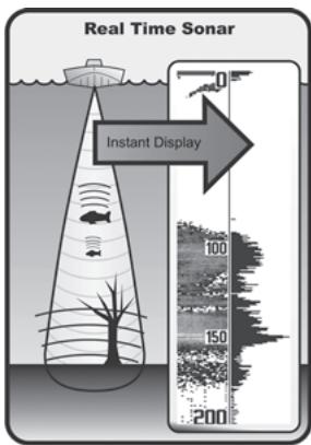
SONAR is an acronym for Sound and NAVIGATION Ranging. Sonar utilizes precision sound pulses or "pings" which are emitted into the water in a teardrop-shaped beam.
The sound pulses "echo" back from objects in the water such as the bottom, fish and other submerged objects. The returned echoes are displayed on the LCD screen. Each time a new echo is received, the old echoes are moved across the LCD, creating a scrolling effect.
When all the echoes are viewed side by side, an easy to interpret "graph" of the bottom, fish and structure appears.
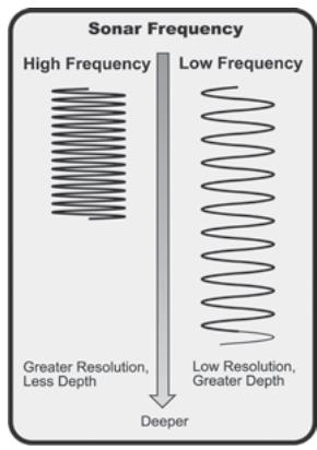
The sound pulses are transmitted at various frequencies depending on the application. Very high frequencies (455 kHz) are used for greatest definition but the operating depth is limited. High frequencies (200 kHz) are commonly used on consumer sonar and provide a good balance between depth performance and resolution. Low frequencies (83 kHz) are typically used to achieve greater depth capability.
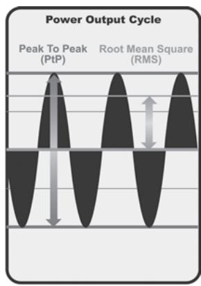
The power output is the amount of energy generated by the sonar transmitter. It is commonly measured using two methods:
- Root Mean Square (RMS) measures power output over the entire transmit cycle.
- Peak to Peak measures power output at the highest points.
The benefits of increased power output are the ability to detect smaller targets at greater distances, ability to overcome noise, better high speed performance and enhanced depth capability.
High Definition Side Imaging Sonar
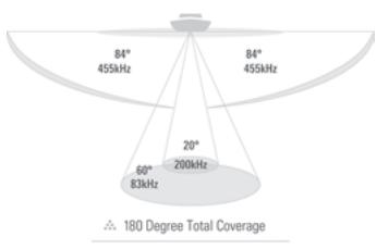
Your 900 Series™ 997c SI Combo uses Side Imaging sonar to provide a wide yet precise survey of a large area of water, including detailed bottom topography and fish-attracting structure orientation. The Side Imaging transducer returns are processed into an image similar to an aerial photograph. Typically, the Side Imaging sonar can search an area that is 720 feet wide (360 to each side), with a typical depth performance of 150 feet when the Side Imaging Sonar frequency is set for 455kHz . The side beams can be operated at one of two frequencies: 455 kHz or 800 kHz. Selecting 800 kHz produces the sharpest image but the search area to each side and the depth capability are limited as compared to the 455 kHz frequency. See What's on the Side Imaging Display and Understanding Side Imaging for more information.
60 Degree Total Coverage

Bottom Coverage = 1× Depth
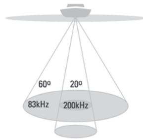
DualBeam PLUS™ Sonar
Your 900 Series™ Fishing System uses a 200/83 kHz DualBeam PLUS™ sonar system with a wide (60°) area of coverage. DualBeam PLUS™ sonar has a narrowly focused 20° center beam, surrounded by a second beam of 60°, expanding your coverage to an area equal to your depth. In 20 feet of water, the wider beam covers an area 20 feet wide. The 20° center beam is focused on the bottom, to show you structure, weeds and cover. The 60° wide beam is hunting for fish in the wide coverage area. DualBeam PLUS™ sonar returns can be blended together, viewed separately or compared side-by-side. DualBeam PLUS™ is ideal for a wide range of conditions - from shallow to very deep water in both fresh and salt water. Depth capability is affected by such factors as boat speed, wave action, bottom hardness, water conditions and transducer installation.
90 Degree Total Coverage

Bottom Coverage = 2× Depth
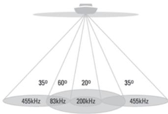
QuadraBeam PLUS™ Sonar
(optional-purchase QuadraBeam PLUS™ transducer only)
Your 900 Series™ 997c Combo supports the optional-purchase QuadraBeam PLUS™ transducer. QuadraBeam PLUS™ sonar provides an extremely wide (90°) area of coverage. QuadraBeam PLUS™ starts with two fan-shaped 35° 455 kHz Side Structure locating sonar beams to spot fish, bait and structure to the left and right of the boat over an area of the bottom that's always equal to twice your depth.
For a detailed view below the boat, QuadraBeam PLUS™ uses DualBeam PLUS™ technology, with precision 20^ and wide 60^ beams. QuadraBeam PLUS™ finds more fish faster, and can even tell you where to put your bait by showing if fish are to the left, right or directly beneath your boat.
Universal Sonar 2
Your 900 Series™ Fishing System supports Universal Sonar 2, a state-of-the-art, integrated and protected transducer that is built into the lower unit of Minnkota trolling motors. With Universal Sonar 2, all wiring is concealed inside the indestructible composite shaft—out of sight and out of harm's way, with no clamps, ties, or exposed wires. Universal Sonar 2 features new temperature sensing and the performance of DualBeam PLUS™ technology. An expanded view and greater bottom detail gives you a totally new perspective of the water below, along with optimal sonar performance to help you find fish.
How GPS and Cartography Work
Your 900 Series™ Fishing System also supports GPS and chartplotting, and uses GPS and sonar to determine your position, display it on a grid, and provide detailed underwater information. The Global Positioning System (GPS) is a satellite navigation system designed and maintained by the U.S. Department of Defense. GPS was originally intended for military use; however, civilians may also take advantage of its highly accurate position capabilities, typically within +/- 10 meters, depending on conditions. This means that 95% of the time, the GPS receiver will read a location within 10 meters of your actual position. Your GPS Receiver also uses information from WAAS (the Wide Area Augmentation System), EGNOS (the European Geostationary Navigation Overlay Service), and MSAS (the MTSAT Satellite Augmentation System) satellites if they are available in your area.
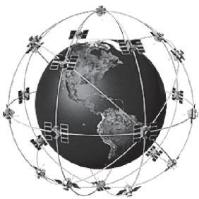
GPS uses a constellation of 24 satellites that continually send radio signals to the earth. Your present position is determined by receiving signals from up to 16 satellites and measuring the distance from the satellites.
All satellites broadcast a uniquely coded signal once per second at exactly the same time. The GPS receiver on your boat receives signals from satellites that are visible to it. Based on time differences between each received signal, the GPS receiver determines its distance to each satellite. With distances known, the GPS receiver mathematically triangulates its own position. With once per second updates, the GPS receiver then calculates its velocity and bearing.
The GPS Receiver included with your 900 Series™ Fishing System allows you to combine easy-to-use FishingGPS® chartplotter and navigation capabilities with advanced fishfinding.
The following GPS functionality is currently supported by the 900 Series™ Fishing System when it is connected to the included GPS receiver:
View current position
View current track (breadcrumb trail)
View precision speed and heading from your GPS receiver
- Save tracks, waypoints and routes
- Travel a route and navigate from one waypoint to the next.
Your 900 Series™ supports Navionics® Gold, HotMaps™ and HotMaps™ Premium on MMC or SD card media.
NOTE: Your 900 Series™ does not support Navionics® Classic Charts, only Navionics® Gold, HotMaps™, and HotMaps™ Premium.
Your unit also comes with a built-in UniMap™ with a more detailed map of North America (Domestic models) or a more detailed map of Europe and Southeast Asia, including Australia and New Zealand (International models).
Your 900 Series™ uses the GPS Receiver to determine the position of the boat automatically, and uses the zoom level settings on a particular view to select the best chart to display. See Viewing Cartography for more information.
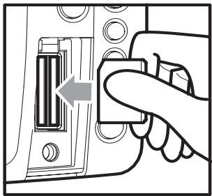
Inserting an MMC/SD into the Card Slot
Multi-Media Card (MMC)/SD Slot
Your 900 Series™ Fishing System also has a multi-media card (MMC)/SD slot that is used to insert optional-purchase cards containing additional detailed maps. If you insert an MMC/SD that contains a more detailed chart for a particular location, your 900 Series™ Fishing System will retrieve that chart and display it automatically. Use the
illustration to locate the position of the MMC/SD slot cover, remove the MMC/SD slot cover, then insert the MMC/SD into the slot. The label on the MMC/SD should face toward the left side of the unit. Press down on the card until it clicks into place and replace the slot cover. Then, replace and tighten snugly - do NOT overtighten, as this will not improve water resistance, and may damage the cover.
Software Updates
Use the MMC/SD slot to update the software version of your control head. To update the software in your control head, plug in the appropriate MMC/SD card that contains a software update file; the unit will recognize it, will tell you what software version your control head is currently running, and will ask you if you want to update the software in the unit to match that on the MMC/SD card. You can obtain software updates from the www.humminbird.com website.
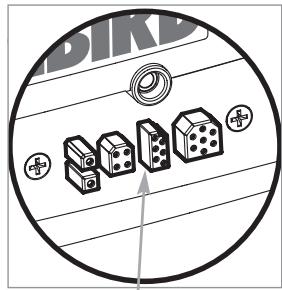
Accessory Bus
Accessory Bus
Use the Accessory Bus to expand the functionality of your 900 Series™. Accessories plug directly into the 900 Series™, enabling Advanced features such as WeatherSense® and the SmartCast® Wireless Sonar Link. Additional tabs and menu choices will be added to the menu system automatically when an accessory is plugged into the unit. In addition, multiple accessories can be attached simultaneously. See Accessories Menu Tab and 900 Series™ Accessories in this manual, as well as your accessory Operations Manual for additional details.
NOTE: Accessories to enable WeatherSense® and the SmartCast® Wireless Sonar Link require separate purchases. You can visit our website at www.humminbird.com or contact our Customer Resource Center at 1-800-633-1468 for additional details.
Installation Overview
Please read all instructions that are relevant for your configuration before beginning the installation process.
NOTE: Installation procedures will depend on product configuration.
The 900 Series™ has a wide variety of configurations.
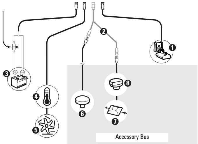
1 Sonar Transducer w/Temperature
2 Optional "Y" Cable
3 Power
4 Temperature/Speed
Speed through water 5
GPS Receiver 6
WeatherSense
SmartCast Wireless Sonar Link 8
Inside the boat there is often a channel or conduit used for other wiring, this can be used to route cables. Be sure to route the cable as far as practical from the antenna cable of VHF radios or tachometer cables to reduce the possibility of interference. The transducer and GPS receiver cables should not be cut, and care should be used not to damage the cable insulation.
Basic installation tasks that you must perform include:
- Installing the control head (choosing either gimbal or in-dash mounting, where in-dash mounting requires a separate purchase)
- Installing the transducer (choosing either the transom mount, inside the hull mount, or trolling motor mounting method)
- Installing the GPS Receiver (if included)
- Testing the complete installation and locking the transducer position.
NOTE: Accessories may require a separate purchase. You can visit our website at www.humminbird.com to order these accessories online or contact our Customer Resource Center at 1-800-633-1468.
Control Head Installation
You have two choices for mounting your 900 Series™ control head, Gimbal mounting, where you use a surface on the boat, such as the dash, to mount the control head so that it can be tilted up or down, or In-dash mounting, which requires a separate purchase.
Gimbal Mounting the Control Head
If you are gimbal mounting the Humminbird® 900 Series™, you can pre-assemble the unit in order to plan the best mounting location.
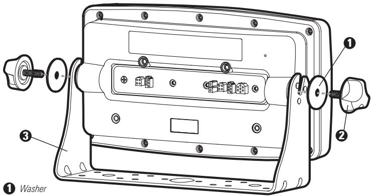
Washer
Gimbal Knob
Gimbal Bracket
In addition to the hardware supplied with your control head, you will need a powered hand drill and various drill bits, various hand tools, including a Phillips head screwdriver, a socket wrench and a flat head screwdriver, a marker or pencil, safety glasses and dust mask, and marine-grade silicone sealant.
- Place the control head into the gimbal bracket. Make sure that the straight side of the gimbal arm is against the back side of the control head.
- Place a 1'' (25 mm) diameter black washer on the gimbal knob and then thread the knob and washer into the housing. Tighten the gimbal knob to secure the 900 Series™ control head to the mount. Repeat step 2 for the other side.
You can now place the control head in various locations to decide which is best for mounting. Rotating the mounting bracket to the top of the control head will allow for overhead mounting. The chosen mounting area should allow for sufficient room so the control head can pivot through the full tilt range and allow for easy removal and installation.
NOTE: You can drill the cable pass hole underneath the gimbal bracket, allowing you to thread the cables through the knock-out holes in the mount; however, if you cannot drill the hole directly under the mounting bracket, then you will need to drill the cable pass hole behind the bracket, and will need to mount the hole cover there instead.
NOTE: When drilling holes in fiberglass hulls, it is best to start with a smaller bit and use progressively larger drill bits to reduce the chance of chipping or flaking the outer coating. Fill all holes with marine grade silicone sealant.
NOTE: You must have underside access to the mounting location to pass the cables through to the surface. Also, make sure that the mounting surface is adequately supported to protect the control head from excessive wave shock and vibration and provide visibility while in operation.
- After the mounting location has been determined, loosen the gimbal knobs and remove the control head from the gimbal bracket.
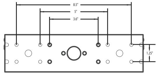
NOTE: Alternate hole patterns are available on the gimbal mounting bracket, and may match existing holes on the boat. You may choose to use one of these alternate hole patterns.
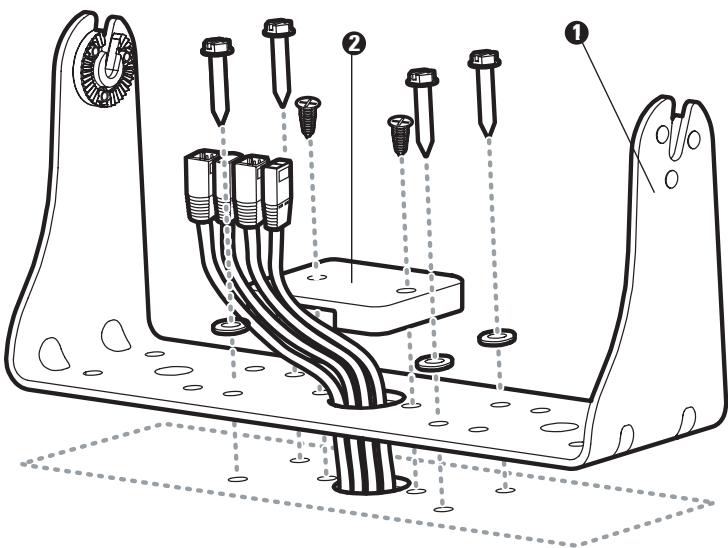
- Place the gimbal bracket in the chosen position on the mounting surface and mark the four mounting screw locations using a pencil or center punch.
NOTE: Go to the installation instructions applicable to your transducer, GPS Receiver and accessories. Make the required installations and then run the cables to your control head mounting location. Do not cut any cabling (except the power cable). If your cables are too short, extensions are available from your local dealer or online from www.humminbird.com.
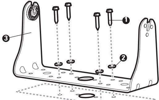
1 Mounting Screws
Gimbal Mounting Bracket 3
Washer
5. Set the gimbal bracket aside and drill the four mounting screw holes using a 5/32'' (4.0 mm) drill bit.
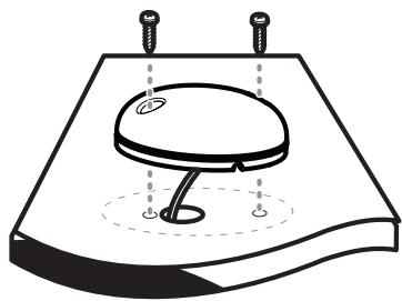
6a. If the cables must pass through a hole directly beneath the mounting bracket, mark and drill an additional 1'' (25 mm) hole centered between the four mounting holes. Route the cables through the 1'' hole. Place the hole cover over the mounting surface
hole, then use it to mark the position of the two mounting screws. Remove the hole cover, drill the two mounting holes using a 9/64" bit. Do not install the hole cover at this time.
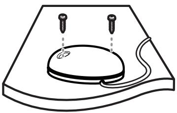
6b. If the cables cannot be routed directly beneath the mounting bracket, mark and drill a 1'' (25 mm) hole that will allow you to run the cables close to the bracket. Pass the cables through the 1'' (25 mm) hole, routing the cables through the grommet and pressing the grommet into place. Place the hole cover over the mounting surface hole, then use it to mark the position of the two mounting screws. Remove the hole cover, drill the two mounting holes using a 9/64'' (3.5 mm) bit, fill them with marine-grade silicone, then replace the hole cover and insert the #8 Phillips countersink wood screws. Hand-tighten only.
- Place the mounting bracket on the mounting surface aligned with the drilled holes and fill the mounting holes with marine grade silicone. Insert the four #10 Slotted-Hex wood screws into the mounting holes. Hand-tighten only.
- If the cable pass through hole is beneath the mounting bracket, you will need to install the hole cover. Place the hole cover over the mounting bracket cable pass thru hole and align with holes drilled in step 6a. Insert the #8 Phillips countersink wood screws. Hand tighten only.
NOTE: Be sure that the cables pass through the slots on the hole cover and that there is enough cable slack to allow for the control head to pivot through its full tilt range. Extra cable slack will also help when connecting/disconnecting the cables.
Cables Routed Directly Beneath Mounting Bracket
Gimbal Bracket
2 Hole Cover
Cables Routed Behind Mounting Bracket
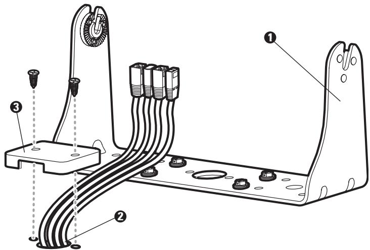
Gimbal Bracket
2Grommet
3 Hole Cover
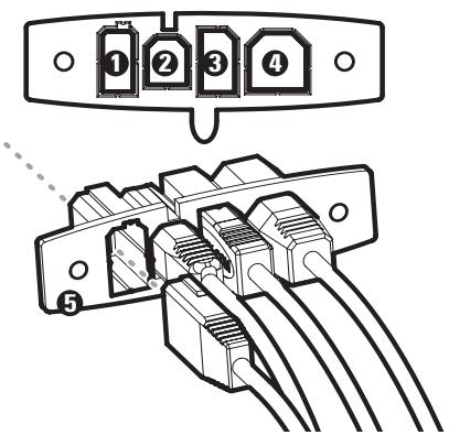
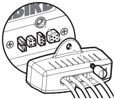
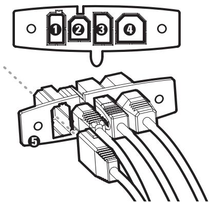
- Insert cable connectors into the proper recesses on the cable collector insert. The cable connectors are keyed to prevent reverse installation, so be careful not to force the connectors into the wrong slots. If you don't have a cable for every hole in the insert, install the blank plugs to protect the control head from the weather.
Power
Temp/Speed
3 Communications
4 Transducer
5 Cable Collector Insert
Plug Cable Connector Assembly to Back of Control Head
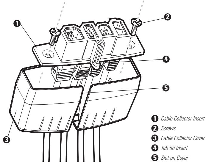
- While holding cables in place in the cable collector insert, thread the cables through the slot in the bottom of the cable collector cover, line up the cable collector insert and cover, then slide the cover into place on the insert.
NOTE: The tab on the Cable Collector insert goes into the slot on the cover.
- Attach the cable collector insert to the cable collector cover using the 2 Phillips screws provided.
- Place the control head back onto the mounting bracket. Plug in the cable collector assembly to the back of the control head. Cable connectors and cable sockets are keyed to prevent reverse installation, so be careful not to force the connectors into the wrong sockets. Once the cable collector and all cables are plugged into the back of the control head, lock the assembly into place by threading the knurled screw into the threaded insert on the back of the housing. Adjust the control head to the desired viewing angle and secure by tightening the gimbal knobs.
NOTE: You may wish to dress the cabling with nylon wire ties in order to hold the cables together and create a cleaner assembly.
The Humminbird® 900 Series™ control head is now ready for operation.
Connecting the Control Head Power Cable to the Boat
A 6^ (2 m) long power cable is included to supply power to the control head. You may shorten or lengthen the cable using 18 gauge multi-stranded copper wire.
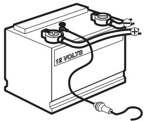
CAUTION: Some boats have 24 or 36 Volt electric systems, but the control head MUST be connected to a 12 VDC power supply.
The control head power cable can be connected to the electrical system of the boat at one of two places: a fuse panel usually located near the console, or directly to the battery.
NOTE: Make sure that the power cable is disconnected from the control head at the beginning of this procedure.
NOTE: Humminbird® is not responsible for over-voltage or over-current failures. The control head must have adequate protection through the proper selection and installation of a 3 amp fuse.
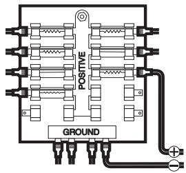
1a. If a fuse terminal is available, use crimp-on type electrical connectors (not included) that match the terminal on the fuse panel. Attach the black wire to ground (-), and the red wire to positive (+) 12 VDC power. Install a 3 amp fuse (not included) for protection of the unit. Humminbird® is not responsible for over-voltage of over-current failures.
or...
1b. If you need to wire the control head directly to a battery, obtain and install an inline fuse holder and a 3 amp fuse (not included) for the protection of the unit. Humminbird® is not responsible for overvoltage or over-current failures.
NOTE: In order to minimize the potential for interference with other marine electronics, a separate power source (such as a second battery) may be necessary.
You are now ready to install the transducer. Find the section that refers to your specific transducer installation method.
Transducer Installation
There are two different installation methods for your transducer:
Transom Transducer
- Trolling Motor Transducer.
Find the section that describes the method of installation you will be using.
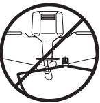
The Side Imaging transducer has some special requirements because of its side viewing capabilities:
- The Side Imaging transducer must NOT have anything obstructing the 'view' of the side looking beams, i.e. nothing can be in the line of sight of these beams (not a hull, motor, or other transducer, etc).
NOTE: You may need to tilt the motor up and out of the way when using the side looking beams. - In order for the side beams to be displayed accurately, the transducer must be mounted so that it is looking straight down in the water when the boat is in the water.
Transducer Position
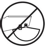
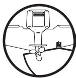
Motor Position
NOTE: If the included transducer will not work for your application, you may exchange it, NEW and UNASSEMBLED, with mounting hardware included, for a transducer appropriate for your application - often at very little or no charge depending on the transducer. Call the Humminbird® Customer Resource Center at 1-800-633-1468 for details and pricing, or visit www.humminbird.com.
NOTE: Due to the wide variety of hulls, only general instructions are presented in this installation guide. Each boat hull represents a unique set of requirements that should be evaluated prior to installation. In addition to the hardware supplied with your transducer, you will need a powered hand drill and various drill bits, various hand tools, including a ruler or straightedge, a marker or pencil, safety glasses and dust mask, and marine-grade silicone sealant.
NOTE: Please read all instructions carefully and completely before beginning the installation process.
NOTE: When drilling holes in fiberglass hulls, it is best to start with a smaller bit and use progressively larger drill bits to reduce the chance of chipping or flaking the outer coating.
Transom Transducer Installation
If you will be installing a transom mounted transducer, use the procedures in this section. There are two pieces to the transducer mount assembly: the pivot, and the bracket. Your transducer comes with a two-piece metal and plastic bracket assembly. There are several procedures you will have to perform in order to install a transom-mounted transducer. They are:
- Determine transducer mounting location
- Mount the bracket to the boat
- Attach the pivot to the transducer
- Mount the transducer pivot assembly to the bracket
- Adjust the running position of the transducer
- Route the transducer cable
- Perform a final test of the transom transducer installation.
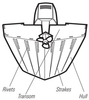
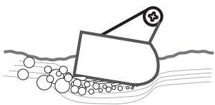
Areas of Possible Turbulence
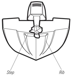
Stepped Hull
To determine transducer mounting location:
NOTE: If transom mounting is not possible because of a stepped hull or cavitation noise, trolling motor installation may be an option. See Rolling Motor Transducer Installation for more information.
-
First, determine the best location on the transom to install the transducer. Consider the following to find the best location:
-
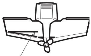
It is very important to locate the transducer in an area which is relatively free of turbulent water. As a boat moves through the water, turbulence is generated by the weight of the boat, and the thrust of the propeller(s) - either clockwise or counter-clockwise. This turbulent water is normally confined to areas immediately aft of ribs, strakes or rows of rivets on the bottom of the boat, and in the immediate area of the propeller(s). Clockwise propellers create more turbulence on the port side. On outboard or inboard/outboard boats, it is best to locate the transducer at least 15^ (380 mm) to the side of the propeller(s).
Deadrise Angle
-
The best way to locate turbulence-free water is to view the transom while the boat is moving. This method is recommended if maximum high-speed operation is a high priority. If this is not possible, select a location on the transom where the hull forward of this location is smooth, flat and free of protrusions or ribs.
-
The hydrodynamic shape of your transducer allows it to point straight down without deadrise adjustment.
- On boats with stepped hulls, it may be possible to mount the transducer on the step. Do not mount the transducer on the transom behind a step to avoid popping the transducer out of the water at higher speeds; the transducer must remain in the water for the control head to maintain the sonar signal.
- If the transom is behind the propeller(s), it may be impossible to find an area clear from turbulence, and a different mounting technique or transducer type should be considered (see Trolling Motor Transducer Installation).
- The Side Imaging transducer must NOT have anything obstructing the 'view' of the side looking beams, i.e. nothing can be in the line of sight of these beams (not a hull, motor, or other transducer, etc).
To mount the transducer bracket to the boat:
- Remove the transducer mounting template from this manual. See Appendix A for the Transducer Mounting Template.
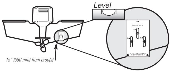
-
Hold the template on the transom of the boat in the location where the transducer will be installed. Align the template vertically, matching the lower edge of the transom with the bottom corner of the template. If your propeller moves clockwise as the boat moves forward, mount the transducer on the starboard side, and use the bottom left corner of the template. If your propeller moves counterclockwise as the boat moves forward, mount the transducer on the port side, and use the bottom right corner of the template.
-
Using a pencil or punch, mark the three mounting holes on the transom. Do not mark or drill any other holes at this time.
- Using a 5/32'' (4.0 mm) bit, drill the three holes to a depth of approximately 1'' (25 mm). On fiberglass hulls, it is best to use progressively larger drill bits to reduce the chance of chipping or flaking the outer coating. Use a marine-grade silicone sealant to fill the drilled holes.
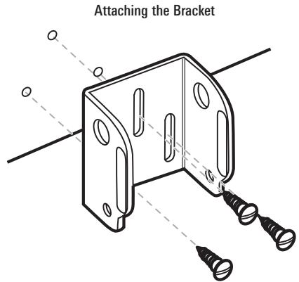
- Align the metal mounting bracket with the mounting holes. The center slot should be above the two outer slots. (This bracket and all other hardware supplied is top quality stainless steel for maximum strength and corrosion protection.) Insert the three 1'' (25 mm) flat head wood screws into the drilled holes, but do not completely tighten.
To attach the pivot to the transducer:
- Attach the pivot to the transducer body, using the two 1/4'' - 20 × 5/8'' (16 mm) machine screws, toothed washers, and square nuts. The toothed washers must fit on the inside of the transducer ears, between the pivot and the ears. The square nuts will be prevented from rotating by the pocket in the back of the pivot. An Allen wrench is provided which fits all the 1/4'' - 20 screws, but do not fully tighten the screws at this time.
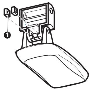
Insert the square nuts
2 Toothed Washer
3 Pivot
4 Machine Screw
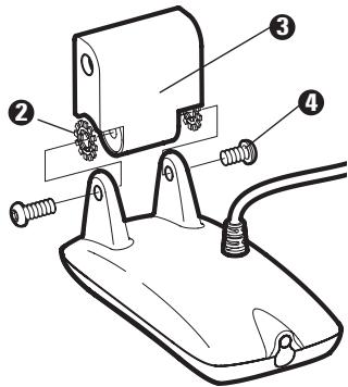
Attach the Pivot
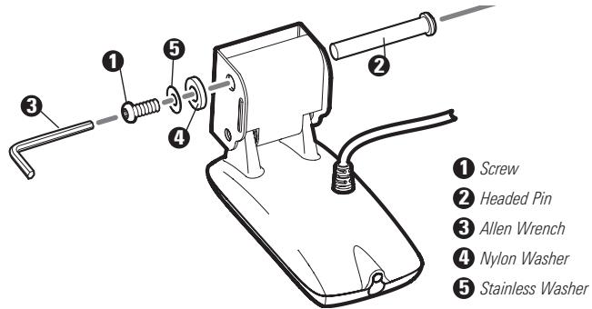
To mount the transducer pivot assembly to the bracket:
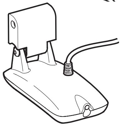
- Slide the assembled transducer into the metal bracket from the bottom, aligning the large hole at the top of the bracket with the hole in the pivot.
- Insert the headed pin through the pivot holes in the bracket and pivot. The headed pin can be inserted from either side of the bracket.
- Place the nylon washer over the opposite end of the headed pin. Place the stainless washer over the 1/4'' - 20 × 5/8'' (16 mm) screw threads, then insert into the opposite end of the headed pin and finger tighten only. The screw has a thread locking compound on the threads to prevent loosening, and should not be fully tightened until all adjustments are made.
NOTE: The running position of the transducer is now completely adjustable. Subsequent adjustment may be necessary to tweak the installation after high speed testing.
To adjust the running position of the transducer:
The transducer mounting bracket allows height and tilt adjustment, while the pivot bolt allows angular adjustment. These adjustments will help reduce cavitation. Initially, adjust the transducer as described in the following paragraphs. Further adjustment may be necessary to refine the installation after high-speed testing.
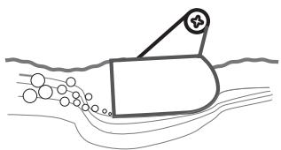
Normal Cavitation
Cavitation that will cause erratic sonar readings
- First, adjust the pivot angle of the transducer body, so it is parallel with the length of the hull of the boat.
- Fully tighten the two pivot screws, using the supplied Allen wrench. Access to the pivot screws is provided by the lower holes in the side of the mounting bracket. It may be necessary to re-tighten the pivot bolt after initial use as the plastic may still be conforming to the pressure from the lock washers.
Tighten the Mounting Screws
-
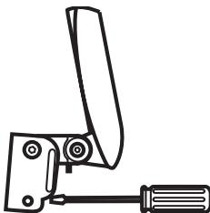
Adjust the height of the assembly so the face of the transducer is 1/8'' (3 mm) to 1/4'' (6 mm) beneath the bottom of the transom, and fully tighten the three mounting screws.
-
In order to gain access to the mounting screws, the transducer assembly must be pivoted up in the bracket as shown. Be careful not to alter the running angle as some force is necessary to pivot the assembly.
-
If access to the top mounting hole is not possible due to the selected height of the transducer, fully tighten the two lower screws, then simply remove the headed pivot pin and the transducer assembly, and tighten the top screw, then reassemble.
- Confirm that the pivot angle has not changed and that all mounting screws are fully tightened.
To route the transom transducer cable:
The transducer cable has a low profile connector that must be routed to the point where the control head is mounted. There are several ways to route the transducer cable to the area where the control head will be installed. The most common procedure routes the cable through the transom into the boat.
NOTE: Your boat may have a pre-existing wiring channel or conduit that you can use for the transducer cable.
- Unplug the other end of the transducer cable from the control head. Make sure that the cable is long enough to accommodate the planned route by running the cable over the transom.
CAUTION! Do not cut or shorten the transducer cable, and try not to damage the cable insulation. Route the cable as far as possible from any VHF radio antenna cables or tachometer cables to reduce the possibility of interference. If the cable is too short, extension cables are available to extend the transducer cable up to a total of 50^ (15 m). For assistance, contact the Customer Resource Center at www.humminbird.com or call 1-800-633-1468 for more information.
NOTE: Since the transducer may need to pivot up to 90^ in the bracket if it strikes an object, make sure there is sufficient cable slack to accommodate this motion. It is best to route the cable to the side of the transducer so the cable will not be damaged by the rotation of the transducer.
- If you will be routing the cable through a hole in the transom, drill a 5/8'' diameter (16 mm) hole above the waterline. Route the cable through this hole, then fill the hole with marine-grade silicone sealant and proceed to the next step immediately.
Routing the Cable
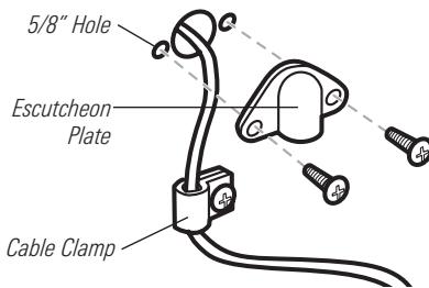
- Place the escutcheon plate over the cable hole and use it as a guide to mark the two escutcheon plate mounting holes. Remove the plate, drill two 9 / 64'' (3.5 mm) holes, then fill both holes with marine-grade silicone sealant. Place the escutcheon plate over the cable hole and attach with two # 8 × 5 / 8'' (16 mm) wood screws.
- Route and secure the cable by attaching the cable clamp to the transom; drill one 9/64'' dia. (3.5 mm) x 5/8'' deep (16 mm) hole, then fill hole with marine-grade silicone sealant, then attach the cable clamp using a # 8 × 5/8'' (16 mm) screw.
- Plug the other end of the transducer cable back into the control head connection holder.
To perform a final test of the transom transducer installation:
After transom transducer installation, please perform the final testing and then finalize the installation (see Test and Finish the Transducer Installation).
Trolling Motor Transducer Installation
If you want to install the transducer on a trolling motor, use this procedure. Several styles of the transducer are compatible with trolling motor mounting. If you have a trolling motor bracket, refer to the separate installation instructions that are included with the bracket.
NOTE: After trolling motor transducer installation, please perform the final testing and then finalize the installation (see Test and Finish the Transducer Installation).
Trolling Motor Transducer Options
If you don't have a trolling motor transducer, there are several options:
-
You may purchase a Trolling Motor Adapter kit that will allow you to mount the transducer on the trolling motor.
-
You may also exchange your NEW and UNASSEMBLED transducer (with mounting hardware included) for a trolling motor transducer.
There are also several transducer switches available that support the following configurations:
- Two control heads with one transducer
- Two transducers with one control head.
NOTE: Call the Humminbird® Customer Resource Center (1-800-633-1468) for details and pricing, or visit www.humminbird.com for more information.
Test and Finish the Transducer Installation
When you have installed both the control head, the transducer, and accessories and have routed all the cables, you must perform a final test before locking the transducer in place. Testing should be performed with the boat in the water, although you can initially confirm basic operation with the boat out of the water.
- Press the POWER/LIGHT key once to turn the control head on. There will be an audible chirp when the key is pressed correctly. If the unit does not power-up, make sure that the connector holder is fully seated and that power is available.
- If all connections are correct and power is available, the control head will enter Normal operation. If no transducer is detected (or one is not connected), the unit will go into Simulator mode and will indicate this by displaying the word Simulator on the control head display.
NOTE: The transducer must be submerged in water for reliable transducer detection.
-
If the bottom is visible on-screen with a digital depth readout, the unit is working properly. Make sure that the boat is in water greater than 2 ft (.6 m) but less than the depth capability of the unit, and that the transducer is fully submerged, since the sonar signal cannot pass through air.
-
If the unit is working properly, gradually increase the boat speed to test high-speed performance. If the unit functions well at low speeds but begins to skip or miss the bottom at higher speeds, the transducer requires adjustment. Angling the rear of the transducer downward and/or lowering the transducer farther into the water will help achieve depth readings at high speeds. If the left side of the fish arch is longer than the right side, then the back of the transducer is angled too far downward. If the right side of the fish arch is longer than the left side, then the back of the transducer is angled too far upwards.
NOTE: It may not always be possible to get symmetrical fish arches and high speed depth readings at the same time. Due to the wide variety of boat hulls, however, it is not always possible to obtain high speed depth readings.
NOTE: It is often necessary to make several incremental transducer adjustments before optimum high speed performance is achieved.
Once you have reached a consistently good sonar signal at the desired speeds, you are ready to lock down the transducer settings.
- Mark the transducer bracket location on the transom with a pencil, then pop up the bracket to reveal the mounting screws. Tighten the stainless steel mounting bracket screws to secure in place.
Hand-tighten only!
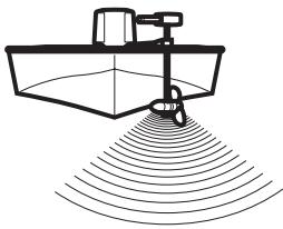
GPS Receiver Installation
To optimize performance of the GPS receiver, mount it in an area that has full exposure to the sky. The effective area of reception is 10^ above the horizon. Different circumstances determine the mounting method appropriate for your GPS receiver.
If you have...
Then use:
| An existing antenna stem with standard 1" - 14 thread stem | Stem Mount with Existing 1" - 14 Thread Stem |
| Access for cable routing under the mounting location | Access Under Mounting Location |
| No access under the mounting location | No Access Under Mounting Location |
The pinouts of the pigtail cable are as follows:
- Red Wire, +12V (output voltage only)
- Black Wire, Ground
- White Wire, NMEA Out.
CAUTION! Please use caution before connecting the red +12V wire to any other NMEA device. This is an output voltage provided by the Fishfinder unit and GPS receiver and should only be connected to those NMEA devices that need a 12 volt input.
Stem Mounting with an Existing 1" - 14 Thread Stem
Follow these steps to stem mount the GPS receiver:
NOTE: If you have an existing stem for mounting the GPS receiver, proceed directly to step 2 of the following procedure.
- Determine the best location to mount your GPS receiver. Preplan and test the cable routing to your control head before any drilling or cutting of your boat surfaces. If you have purchased hardware to stem mount your GPS receiver, follow the instructions included with that hardware to mount the stem (antenna pole).
NOTE: AS-EC10 10' extension cables are available from Humminbird® if your planned routing exceeds 20', (6 m). Maximum cable length, including extensions, should not exceed 50' (16 m).
NOTE: Remember to caulk or seal screw holes and drilled holes as needed to protect your boat from water damage.
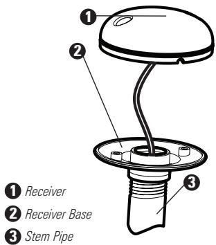
-
Screw on the receiver base to the stem first, making sure that the stem pipe does not protrude from the receiver base. This adds protection to the cable when pulling it through the pipe stem. In addition to this, de-burr the pipe edges to reduce cable abrasion.
-
Use electrical tape to secure the NMEA pigtail to the cable as shown.
NOTE: Leave the NMEA pigtail secured to the cable unless needed. This will make removing the receiver easier.
- Route the GPS receiver cable through the stem and continue with the planned route you chose in step 1.
- Attach the GPS receiver to its base using the included #6 - 7/8" screws.
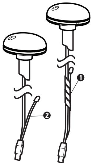
1 NMEA Pigtail Taped
NMEA Pigtail Cable Out
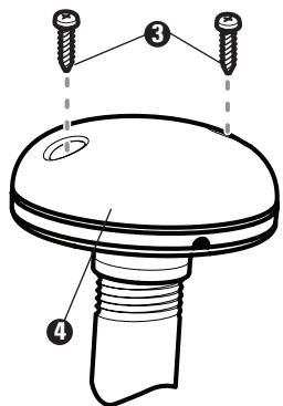
3 Mounting Screws
4 Cable Route
Access Under Mounting Location
Follow these steps to deck mount the GPS receiver when routing the cable down through the mounting location:
- Determine the best location, then test route the 20^ (6 m) cable from the mounting location to the control head.
NOTE: Installation details may vary with unit configuration.
- Mark the mounting location and drill a 3/4'' (19 mm) hole for the cable and cable plug. Route the cable.
- Cover the cable hole with the receiver. Make sure the receiver is flush on the surface and mark the two mounting holes with a pencil or punch.
- Move the receiver to the side and drill two pilot holes using a 9/64" (3.5 mm) bit.
NOTE: Remember to caulk or seal screw holes and drilled holes as needed to protect your boat from water damage.
5. Align the GPS receiver screw holes over the pilot screw holes and attach with the #8 - 1 1/4" Phillips head screws. Hand tighten only!
NOTE: If the mounting surface is thin and made of a lighter material, a backing material may be needed below the mounting surface.
Access Under Mounting Location
No Access Under Mounting Location
No Access Under Mounting Location
Follow these steps to deck mount the GPS receiver in a situation where you must route the cable to the side because there is no space for a cable underneath the mounting location.
- Determine the best location, then test route the cable from the mounting location to the control head.
NOTE: AS-EC10 10^ extension cables are available from Humminbird® if your planned routing exceeds 20^ (6 m). Maximum cable length, including extensions, should not exceed 50^ (16 m).
2. Confirm the cable length is good and route the cable from the receiver to the control head. If holes are required to route the cable, they must be 3/4'' (19 mm) to allow for the cable connector. Secure the NMEA pigtail with electrical tape.
NOTE: Remember to caulk or seal screw holes and drilled holes as needed to protect your boat from water damage.
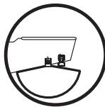
- The GPS receiver has two wire routing notches. Use the cable notch closest to the intended cable route.
- With the cable routed, position the GPS receiver in the planned mounting location and mark the mounting holes with a pencil or punch.
- Move the GPS receiver to the side and drill the two 9/64'' (3.5 mm) pilot holes.
- Align the GPS receiver's screw holes over the pilot screw holes and attach with the #8 - 1 1/4" Phillips head screws. Hand tighten only!
Finish Routing the Cable and Check GPS Receiver Operation
After installing a GPS receiver, you should perform the following procedure to finish routing the GPS cable to the control head and to check to make sure that the control head is working correctly.
- Secure the cable along its path to the control head as needed with cable ties.
- Plug the GPS receiver cable into the Communications port on the control head. See Testing the System Installation to use the System Status start-up option and/or the GPS Diagnostic View to confirm a good installation.
Power
Temp/Speed
3 Communications
4 Transducer
5 Cable Collector Insert
Testing the System Installation
After you have completed the installation of the control head, transducer, and any other accessories such as the GPS receiver, and have made all the cabling connections required, you must test the installation before using the system. Thorough testing should be performed with the boat in the water; however, you can confirm basic operation initially with the boat out of the water as well.
To test the installation:
- Press the POWER/LIGHT key on the control head once to turn on the control head. (There will be an audible chirp to let you know that you pressed the key, and the initial Title screen will appear.) If the unit does not power up, make sure that power is available. While the Title screen is shown on the display, press the MENU key to display
the Start-Up Options menu. Use the UP or DOWN 4-WAY Cursor keys to position the cursor, then the RIGHT Cursor key to select System Status from the Start-Up Options menu (see the Start-Up Options Menu section for more information about these menu choices). The System Status Self Test screen will appear.
NOTE: If you wait too long, the system will default to whichever menu mode happens to be highlighted, and you will have to start again.
- Self Test displays results from the internal diagnostic self test, including unit serial number, Printed Circuit Board (PCB) serial number, software revision, total hours of operation and the input voltage. See System Status for more information about the Self Test.
- From the System Status screen, view accessory connections by pressing the VIEW key. See System Status for more information about the Accessory Test.
NOTE: The speed will be detected only if the paddlewheel has moved since the 900 Series™ has been powered up.
- From the System Status screen, see a GPS Diagnostic View by pressing the View key. GPS Diagnostic View shows a sky chart and numerical data from the GPS receiver. The sky chart shows the location of each visible GPS satellite with its satellite number and a signal strength bar. A dark grey bar indicates that the satellite is being used to determine your current position. A light gray bar indicates that the satellite is being monitored, but is not yet being used. See System Status for more information about the GPS Diagnostic View.
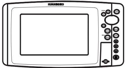
Getting Started - Using Your 900 Series™
Your 900 Series™ Fishing System user interface is easy to use. A combination of keys, different views, and situation-specific, customizable menus allows you to control what you see on the color display. Refer to the following illustration, and see Key Functions, Views, and The Menu System) for more information.
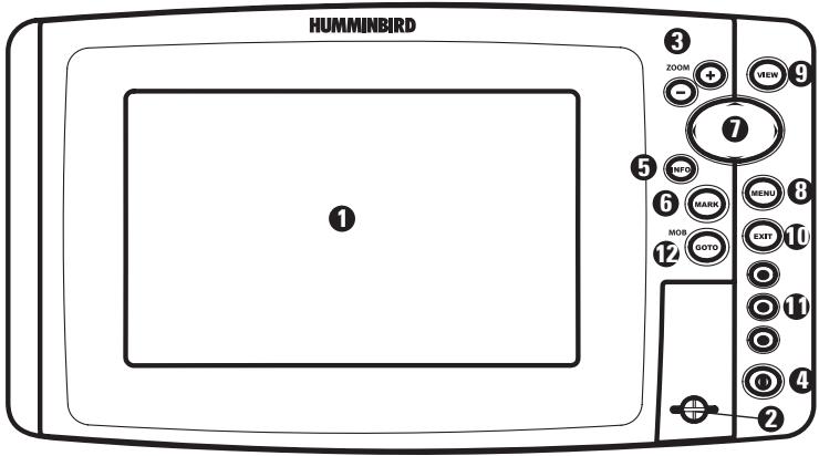
Screen 4-WAY Cursor Control Key 7
2 MMC/SD Card Slot
3 ZOOM (+ / - ) Keys VIEWKey 9
4 POWER/LIGHT Key EXIT Key 10
5 INFO Key View Preset Keys 11
6 MARK Key GOTO Key 12
Powering Up the Control Head
Turn on your 900 Series™ control head by pressing the POWER key. The Title screen is displayed until the 900 Series™ begins operation. Your 900 Series™ will begin Normal or Simulator operation, depending on the presence or absence of a transducer.

HUMMINBIRD
997cx SI Combo
Press MENU for Startup Options
900 Series™ 997cx SI Combo Title Screen
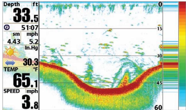
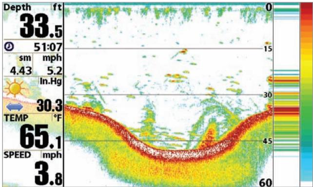
The 900 Series™ can display a variety of useful information about the area under and adjacent to your boat, including the following items:
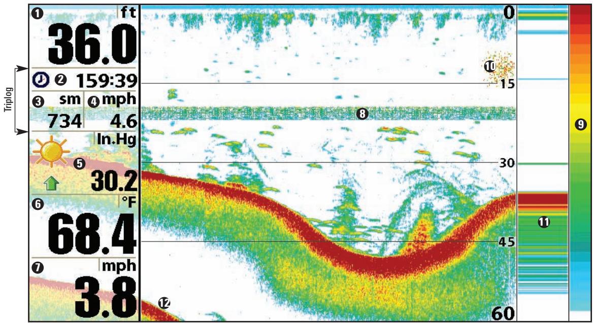
Speed - if a Speed accessory or GPS Receiver is attached, the 900 Series™ can display the speed of the boat, and can keep a triplog of nautical or statute miles traveled.
Thermoclines - layers of water with different temperatures that appear at different depths and different times of the year. A thermocline typically appears as a continuous band of many colors moving across the display at the same depth.
9 Sonar Color Bar - color spectrum indicating low to high sonar intensity returns, where red indicates high intensity and white indicates low intensity.
Bait Ball
RTS® (Real Time Sonar) Window
1 Second Sonar Return - when the sonar signal bounces between the bottom and the surface of the water and back again. Use the appearance of the second return to determine bottom hardness. Hard bottoms will show a strong second return, while soft bottoms will show a very weak one or none at all.
Depth - water depth; can be set to alarm when the water becomes too shallow.
Timer - Elapsed time with Speed accessory or GPS Receiver.
3 Distance - Distance traveled with Speed accessory or GPS Receiver.
4 Average Speed - Average speed reading with Speed accessory or GPS Receiver.
5 Barometric Pressure - Requires optional-purchase WeatherSense
6 Temperature - water surface temperature
Triplog
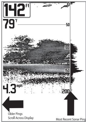
Understanding Sonar History
It is important to understand the significance of the 900 Series™ display. The display does NOT show a literal 3-dimensional representation of what is under the water. Each vertical band of data received by the control head and plotted on the display represents something that was detected by a sonar return at a particular time. As both the boat and the targets (fish) may be moving, the returns are only showing a particular segment of time when objects were detected, not exactly where those objects are in relation to other objects shown on the display.
Real Time Sonar (RTS®) Window
A Real Time Sonar (RTS®) Window appears on the right side of the display in the Sonar View only. The RTS® Window always updates at the fastest rate possible for depth conditions and shows only the returns from the bottom, structure and fish that are within the transducer beam. The RTS® Window plots the depth and intensity of a sonar return. (See Sonar Menu: RTS® Window).
The Narrow RTS® Window indicates the sonar intensity through the use of colors. Red indicates a strong return and blue indicates a weak return. The depth of the sonar return is indicated by the vertical placement of the return on the display depth scale.
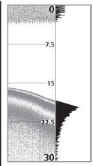
The Wide RTS® Window indicates the sonar intensity through the use of a bar graph. The length of the plotted return provides an indication of whether the return is weak or strong. The depth of the sonar return is indicated by the vertical placement of the return on the display depth scale.
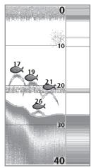
Sonar Bottom Presentation
As the boat moves, the unit charts the changes in depth on the display to create a profile of the Bottom Contour. The type of bottom can be determined from the return charted on the display. A Hard Bottom such as compacted sediment or flat rock appears as a thinner line across the display. A Soft Bottom such as mud or sand appears as a thicker line across the display. Rocky Bottoms have a broken, random appearance.
NOTE: A sloping bottom will be represented as a thicker line across the display. Harder bottoms typically will be displayed with red and softer bottoms typically will be displayed with blue.
The sonar returns from the bottom, structure and fish can be represented as either Structure ID® or WhiteLine®. See Sonar Menu: Bottom View for details on how to set the bottom view.
Structure ID represents weak returns in blue and strong returns in red.
WhiteLine® highlights the strongest sonar returns in white, resulting in a distinctive outline. This has the benefit of clearly defining the bottom on the display.
Understanding Side Imaging
It is important to understand how Side Imaging technology produces the display available on the 900 Series™. The images you see on the display are produced using sonar technology. The special transducer produces three distinct beams – one beam facing down and two beams pointing out to the side. These “side beams” are aimed at right angles to the path of the boat and, unlike the “down beam” which provide conical coverage, the side beams provide coverage which is very thin front to back, yet very wide top to bottom.
The narrow aspect (front to back) of the beam illuminates a small strip of the bottom perpendicular to the direction of the boat. Each time the unit "pings", a strip of data representing all the echoes received by the transducer, are put together on the display to form the image that you see. The rows closest to the boat icon at the top of the display are the most recent sonar data. The information is scrolled down the screen as new data, drawn at the top of the screen, becomes available.
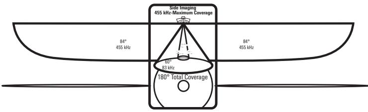
455 kHz provides maximum coverage with 180^ total beam width
The side beams can be operated at one of two frequencies: 455 kHz or 800 kHz. Selecting 800 kHz produces the sharpest image while selecting 455 kHz provides greater bottom coverage area. It is important to understand that when the boat turns, the strips to one side will begin to overlap and the strips on the other side will fan out, providing some distortion to the image. Side beams look out 360 feet, with a depth limitation of 100 to 150 feet, depending on the contour of the bottom and when the side beam frequency selection is set for 455 kHz. Please see the Side Imaging Sonar Tutorial at www.humminbird.com for a more detailed explanation.
Your Side Imaging transducer also provides traditional sonar imaging at 200/83 kHz.
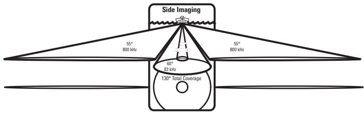
800 kHz provides highest resolution with 130^ total beam width
What's on the Side Imaging Display
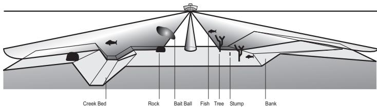
Side Imaging displays a number of easily recognizable features that allow for accurate interpretation of bottom contour and structure. For Side Imaging, the bottom composition determines the intensity of the sonar return. For example, rock and gravel provide a clearer sonar return than mud and sand because of their relative density. Upward slopes that face the transducer reflect sonar better than downward slopes that face away from the transducer. You can find a number of easily recognizable features on the Side Imaging display that allow for accurate interpretation of bottom contour and structure, including the following items:
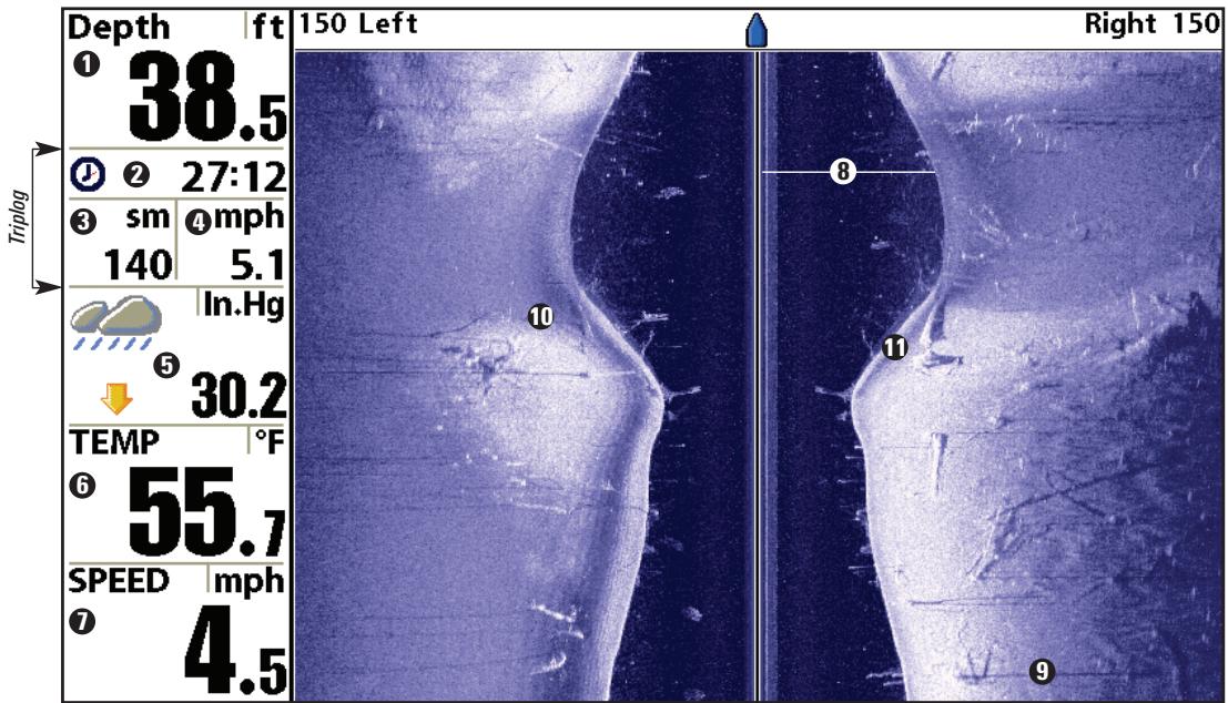
Triplog
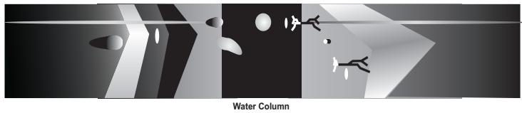
The water column shows the relative depth of the water under the boat at a given time. Variations in the width of the water column show variations in the distance to the bottom as the boat passes over.
9 Shadows result from a lack of reflected sonar from a particular area, and can be more valuable for interpretation than the sonar reflected by the object itself. Use shadows to help you see the image in 3 dimensions, oriented in space. You can gain insight into the actual shape of an object, or the depth to which it has sunk into the bottom, through shadows on the display.
Topography Changes
Bottom Return
Depth - water depth; can be set to alarm when the water becomes too shallow.
Timer - Elapsed time with Speed accessory or GPS Receiver.
3 Distance - Distance traveled with Speed accessory or GPS Receiver.
4 Average Speed - Average speed reading with Speed accessory or GPS Receiver.
5 Barometric Pressure - Requires optional-purchase WeatherSense
6 Temperature - water surface temperature
Speed - if a Speed accessory or GPS Receiver is attached, the 900 Series™ can display the speed of the boat, and can keep a triplog of nautical or statute miles traveled.
Side Imaging Technology: How it works
Side Imaging sonar uses two very precise sonar beams that are directed to either side of the boat and "illuminate" the bottom contour, structure, and fish, and display results in a "picture-like" image.
- Side beams are extremely narrow from front to back, and provide "thin slices" of the bottom for high resolution imaging.
- Side beams can search an area that is 720 feet wide (360 to each side), with a typical depth performance of 150 feet when the side beam frequency selection is set for 455kHz .
The main benefit of Side Imaging sonar to anglers is that it provides an overall survey of a large area of water. This gives you a better understanding of the bottom topography and how structure is oriented for more efficient fishing. Saltwater anglers pick up precise details of popular fishing structure like wrecks, reefs, humps and drop-offs, as well as being able to spot bait balls in open water. Freshwater anglers can see fish-attracting structure such as timber, stumps, rocks and creek beds.
Side Imaging Representation
Side Imaging: On the water Interpretation
Use the following side imaging examples to help you interpret the side imaging display.
Imaging Tips
Boat speed: Side imaging is best performed at boat speeds between 2 to 6 mph. If the boat is stationary, the same information is displayed over and over. If the boat is moving very quickly, there will be gaps between the strips of information. The best boat speed to use will depend on the side range selected. Slower speeds are good for longer ranges, while faster speeds can be used at shorter ranges.
Boat navigation: It is important to understand that when the boat turns, successive beam strips to one side will begin to overlap and the strips on the other side will fan out, providing some distortion to the image. Because of this, the best imaging performance is produced by straight line navigation and minimal side-to-side boat motion (i.e. wave induced, etc.) This applies to navigation by either the main engine or the trolling motor. Minimize turning time and avoid wave action that induces large side-to-side rocking of the boat. For example, if there is a lot of wave activity, try to move the boat so that it is perpendicular to the waves instead of parallel with the waves in order to minimize the side-to-side rocking of the boat.
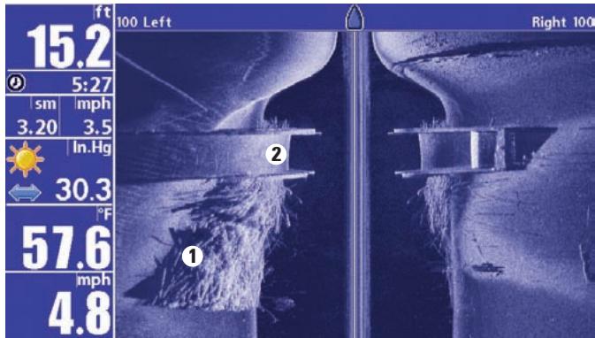
Beam Coverage: When there is an area directly under the boat that does not have SI beam coverage, this area will be covered by the standard 200/83 kHz down-looking beam and displayed in the Sonar views. The net effect of this, on the display, is that a single object may appear as two separate entities when in reality, it is one continuous object. See Submerged Bridge: A Closer Perspective and the Submerged Bridge graphics on the next page for examples of this.
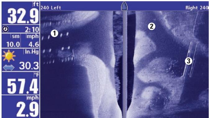
Submerged Bridge, Creek Channel and New Bridge Piling
New bridge pilings
2 Creek channel
Submerged bridge 3
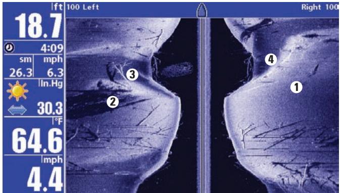
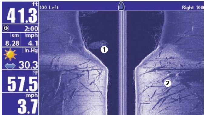
Submerged Ravine with Timber
Possible drop off
2 Submerged timber
Submerged tree
Submerged ravine
3
4
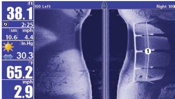
Submerged Bridge: A Closer Perspective
1 Submerged Bridge
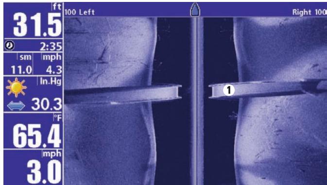
Submerged Bridge, Alternative Perspective
Submerged Bridge
Submerged Standing and Fallen Timber, Plus Bait Fish

Bait fish
Standing and fallen timber 2
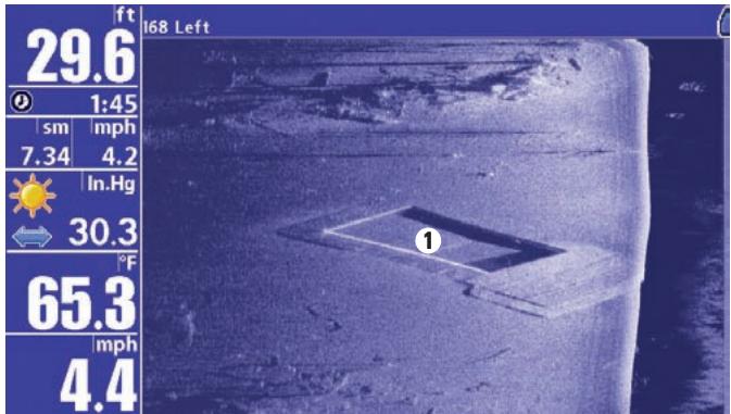
Submerged Swimming Pool

Swimming pool
Submerged Barge with Dumped Logs
Dumped logs
Submerged barge 2
Key Functions
Your 900 Series™ user interface consists of a set of easy-to-use keys that work with various on-screen views and menus to give you flexibility and control over your fishing experience. Your control head has the following keys:
- POWER/LIGHT key
- EXIT key
VIEWkey
4-WAY Cursor Control key - MENU key
- VIEW PRESET keys.
MARK key
GOTO key - INFO key
- ZOOM (+/-) keys.

POWER/LIGHT Key
The POWER/LIGHT key is used to turn the 900 Series™ on and off, and also to adjust the backlight and background color of the display. Press the POWER/LIGHT key to turn the unit on. The Title screen is then displayed until the 900 Series™ begins sonar operation.
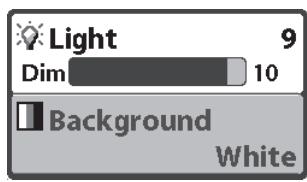
To adjust the backlight or to adjust the display background color, press the POWER/LIGHT key to access the Light and Background menu. Use the 4-WAY Cursor key to select Light or Background and then use the LEFT or RIGHT Cursor key to change the settings. Press EXIT to exit the Light and Background menu.
Press and hold the POWER/LIGHT key for 3 seconds to turn the unit off. A message will appear telling you how many seconds there are until shutdown occurs. Your 900 Series™ should always be turned off using the POWER/LIGHT key. This will ensure that shutdown occurs properly and any menu settings will be saved.

VIEW Key
The VIEW key is used to cycle through all available views. Press the VIEW key to advance to the next view. Repeatedly pressing VIEW cycles through all views available. Views can be hidden to optimize the system to your fishing requirements (see View Menu Tab).

MENU Key
The MENU key is used to access the menu system.
Start-Up Options Menu - Press the MENU key during the power up sequence to view the Start-Up Options menu.
X-Press™ Menu - Press the MENU key once for the X-Press™ Menu. The X-Press™ Menu allows you to access frequently-used settings without having to navigate through the whole menu system. When the X-Press™ Menu is displayed, you can use the UP or DOWN Cursor keys to move to a particular menu choice. As soon as you alter a parameter (using the RIGHT or LEFT Cursor keys) the X-Press™ Menu will collapse temporarily, and the screen will update if it is affected by your menu setting change, allowing you to see the effects of your action immediately. Reactivate the X-Press™ Menu by using the UP or DOWN Cursor keys.
Main Menu - Press the MENU key twice for the tabbed Main Menu System. The Main Menu System is organized under tabbed headings to help you find a specific menu item quickly: Alarms, Sonar, Navigation, Chart, Setup, Views, and Accessories tabs are part of your tabbed Main Menu System. Use the LEFT or RIGHT 4-WAY Cursor Control key to select a tab; then use the DOWN or UP key to select the menu item, and the LEFT or RIGHT key to alter a menu setting.
4-WAY Cursor Control Key
The 4-WAY Cursor Control Key has multiple functions, depending on the situation:
Freeze Frame - Pressing any arrow on the 4-WAY Cursor Control key will freeze the display in the Sonar View and a cursor and cursor dialog box will be displayed. The cursor can be positioned on the Sonar View using the 4-WAY Cursor Control key.
Active Cursor - In any Bird's Eye View, the 4-WAY Cursor Control key controls the motion of the eyepoint. In any Chart View, the 4-WAY Cursor Control key pans the charts.
NOTE: In either Freeze Frame or Active Cursor mode, you can also make the cursor move diagonally by pressing in between two of the arrows on the 4-WAY Cursor Control key..
Menu Selection - Use the DOWN or UP arrow keys to select a menu choice from the menu list, then use the LEFT or RIGHT arrow keys to change a menu setting.
Snapshot and Recording View - In the Snapshot and Recording View, highlighting a recording icon and pressing the Right 4-WAY Cursor Control key starts recording playback, and the Right and Left keys are used to control the speed of playback.
NOTE: Menu choices are implemented and saved immediately - no further action is required.
VIEW PRESET keys
The VIEW PRESET keys are used to program your three favorite views for quick retrieval. Instead of using the VIEW key to cycle through every view to find the one you want, you can program the VIEW PRESET keys to display a specific view immediately. To program each VIEW PRESET key, use the VIEW key to cycle to the view you want to store. Press and hold one of the VIEW PRESET keys for several seconds. A series of audible chirps will be heard indicating that the view has been programmed to the key. You can store up to three views, one on each key.

EXIT Key
The EXIT key has multiple functions, depending on the situation:
- If an alarm is sounding, pressing EXIT will cancel the alarm.
- If a menu tab is selected, pressing EXIT will exit the menu mode and return to the view.
- If a menu is active, pressing EXIT will return to the previous level in the menu system.
- Pressing EXIT will cycle through the available views in reverse order.
- If Freeze Frame is active, pressing EXIT will return to a scrolling display.
- If the Cursor is active, pressing EXIT will remove the cursor from the display.

INFO Key
Press the INFO key while in any navigation view to display information about objects that are nearest to an active cursor.
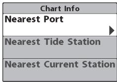
If the cursor is not active, the following menu will be displayed. Use the 4-WAY Cursor Control key to select Nearest Port, Nearest Tide Station or Nearest Current Station, then use the RIGHT Cursor key to display the requested information.
NOTE: The built-in UniMap™ does not contain Port, Tide or Current information.
This information is only available from optional purchase MMC/SD cards.

MARK Key
Press the MARK key while in any view to mark the position of a waypoint, either at the current boat location, or, if the Cursor is active, at the current Cursor location.
The MARK key only functions if you have the GPS receiver connected, or if you have enabled Screen Snapshot from the Accessories menu tab. If you have enabled the Screen Snapshot feature, pressing the MARK key still creates a waypoint, but it also captures the screen image to the optional purchase MMC/SD card.
NOTE: You must have an optional-purchase MMC/SD card installed for the screen snapshot feature to work.
Navigation is not affected by the Screen Snapshot feature. Also, if Screen Snapshot is enabled but there is no GPS receiver connected, pressing the MARK key will capture the screen image and display an error saying that a GPS position fix is required to create a waypoint.

GOTO Key
The GOTO Key has multiple functions, depending on the situation:
- If the Cursor is active, pressing the GOTO key while in any view creates a waypoint and starts navigation towards that waypoint. If the Cursor is not active, pressing the GOTO key displays the list of waypoints, so that you can select the waypoint towards which you want to navigate.
- If the GOTO key is pressed and held for more than 1.5 seconds, the Man Overboard (MOB) function is activated. When MOB is activated, an MOB waypoint, which is a permanent, sharable waypoint with a large, distinctive icon, is created at the boat's current position (regardless of whether the chart cursor is active or not). Any current navigation will be cancelled and the current route discarded without user notification, and MOB navigation begins immediately. The view is switched to the Chart View automatically when MOB is activated, and it is not possible to activate MOB or modify the current route without first canceling MOB navigation. Any press of the GOTO key, or selection of a GOTO menu item, will cause an error beep and a short message will be displayed to the user that will disappear after 2 seconds.
ZOOM (+ / - ) Key
Press the - or + ZOOM keys while in any of the Navigation Views or the Sonar Zoom View to change the scale of the view to appear closer or farther away.

Press the - or + ZOOM keys while in the Side Imaging View to change the scale of the view. The cursor must be active for zoom to work in the Side Imaging View.
Views
The views available on your 900 Series™ are:
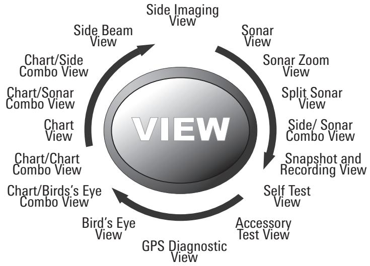
- Side Imaging View
- Sonar View
- Sonar Zoom View
- Split Sonar View
Side/Sonar Combo View - Snapshot and Recording View
Self Test View -
Accessory Test View
GPS Diagnostic View -
Bird's Eye View
Chart/Bird's Eye Combo View
Chart/Chart Combo View
Chart View
Chart/Sonar Combo View
Chart/Side Combo View - Side Beam View (only with optional-purchase QuadraBeam™ PLUS transducer)
Chart/Side Combo View is the default view. When the VIEW key is pressed, the display cycles through the available views. When the EXIT key is pressed, the display cycles through the available views in reverse order. Any view can be hidden or displayed as part of the view rotation using the Views Menu tab.
NOTE: When you change any menu settings that affect the sonar, the view will update immediately (i.e. you don't have to exit the menu to apply the change to the screen).
Views and Readouts
All views have an Information Bar on the left side of the screen, consisting of readouts that are stacked vertically, and that change from view to view. You can customize the information displayed in individual readouts on many views, including suppressing a particular readout so that nothing is displayed; the ability to customize readouts depends on the view and whether you are navigating (see Setup Menu Tab, Select Readouts for more information).
Side Imaging View
Side Imaging View shows a shadowed right- and left-looking view from the boat as the boat passes over the bottom. See Side Imaging: On the Water Interpretation for more information about interpreting the Side Imaging view.
In this view, you can change which side you look at, the sensitivity of the sonar to allow you to see more or less detail, the range of the side beams, the scrolling speed of the chart, and the color scheme of the display, all from the Side Imaging X-Press™ Menu. See Side Imaging X-Press™ Menu, as well as Understanding Side Imaging, for more information.
Freeze Frame - Pressing any arrow on the 4-WAY Cursor Control key will freeze the screen in the Side Imaging View and a cursor and cursor dialog box will be displayed on the screen. The cursor can be positioned on the display using the 4-WAY Cursor Control key to determine the depth of any sonar return. In addition, see the effects of menu setting changes with Instant Image Update.
Pressing the - or + ZOOM keys while in Freeze Frame will zoom the Side Imaging Image around the cursor, allowing for a more detailed inspection of the sonar returns.
Pressing EXIT will exit Freeze Frame and the display will start to scroll.
Side Imaging View
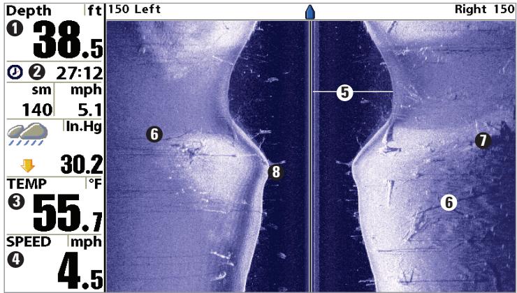
1 Depth
2 Triplog
3 Water Surface Temperature
Speed
Water Column 5
Shadows 6
Topography Changes 7
Bottom Return 8
Sonar View
Sonar View presents a historical log of sonar returns. The most recent sonar returns are charted on the right side of the window; as new information is received, the older information is moved across the display to the left. A scale with Upper and Lower Depth Range readouts appears along the right edge of the Sonar View. The scale indicates the distance from the surface of the water to a depth range sufficient to show the bottom. Depth Range is automatically selected to keep the bottom visible on the display, although you can adjust it manually as well (see Sonar X-Press™ Menu).
Freeze Frame - Pressing any arrow on the 4-WAY Cursor Control key will freeze the screen in the Sonar View and a cursor and cursor dialog box will be displayed on the screen. The cursor can be positioned on the display using the 4-WAY Cursor Control key to determine the depth of any sonar return. The RTS® Window continues to update in Freeze Frame. In addition, see the effects of menu setting changes with Instant Image Update.
Pressing EXIT will exit Freeze Frame and the display will start to scroll.
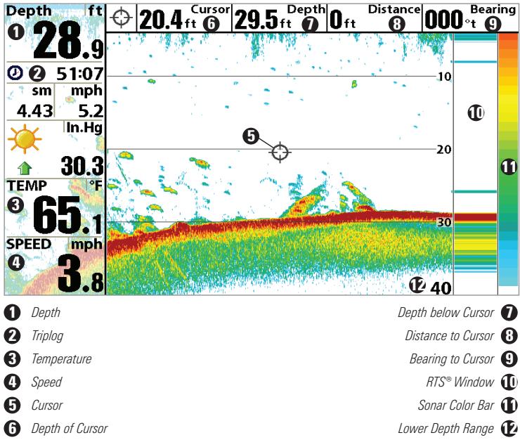
Sonar View
NOTE: If the Depth number is flashing, it means that the unit is having trouble locating the bottom. This usually happens if the water is too deep, the transducer is out of the water, the boat is moving too fast, or for any other reason that the unit can't accurately receive continuous data.
Sonar Zoom View
Sonar Zoom View increases the displayed resolution to separate sonar returns that are very close together, such as those caused by fish suspended close to the bottom or within structure. In Zoom View, the display is split to show a narrow slice of the full range view on the right and the zoomed view on the left. The full range view on the right also contains the Zoom Preview Box that shows what part of the full range view is shown in zoom view on the left; the Zoom Preview Box tracks the bottom in the full range view.
As the depth changes, the zoomed view updates automatically to display a magnified image of the bottom. The Zoom Preview Box shows where the zoomed view is in relation to the full range view. The Zoom Level, or magnification, is displayed in the upper left corner and can be changed to suit conditions. Upper and Lower Zoom Depth Range numbers indicate the depth of the water which is being viewed.
Freeze Frame - Pressing any arrow on the 4-WAY Cursor Control key will freeze the screen in the Sonar Zoom View and a cursor and cursor dialog box will be displayed on the screen. The cursor can be positioned on the display using the 4-WAY Cursor Control key to determine the depth of any sonar return. In addition, see the effects of menu setting changes with Instant Image Update.
Pressing EXIT will exit Freeze Frame and the display will start to scroll.
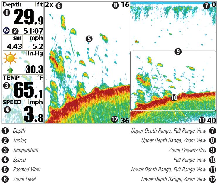
Sonar Zoom View
Split Sonar View
Split Sonar View displays sonar returns from the 83 kHz wide beam on the left side of the screen and displays sonar returns from the 200 kHz narrow beam on the right side of the screen. You can use the Split Sonar View to make side by side comparisons between the sonar returns from the 83 kHz wide beam and the 200 kHz narrow beam.
Freeze Frame - Pressing any arrow on the 4-WAY Cursor Control key will freeze the screen in this view and a cursor and cursor dialog box will be displayed on the screen. The cursor can be positioned on the display using the 4-WAY Cursor Control key to determine the depth of any sonar return. In addition, see the effects of menu setting changes with Instant Image Update.
Pressing EXIT will exit Freeze Frame and the display will start to scroll.
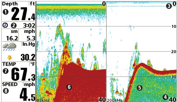
Split Sonar View
1 Depth
2 Triplog
Upper Depth Range
Lower Depth Range
200 kHz Sonar History Window 5
83 kHz Sonar History Window 6
Temperature 7
Speed 8
Side/Sonar Combo View
Side/Sonar Combo View shows regular sonar information and side imaging sonar information in a combination split screen. You can perform any of the functions for either of these views, but only when the view you want to control is selected as the active side (see Sonar X-Press™ Menu: Active Side or Side Imaging X-Press™ Menu: Active Side for more information). You can also adjust the size of the left side of a split screen (see Sonar X-Press™ Menu: Split Position or Side Imaging X-Press™ Menu: Split Position for more information).
In this view, you can change which side you look at, the sensitivity of the sonar to allow you to see more or less, the range of the side beams, the scrolling speed of the chart, and the color scheme of the display.
NOTE: See Side Imaging View and Sonar View for more information about each side of this view.
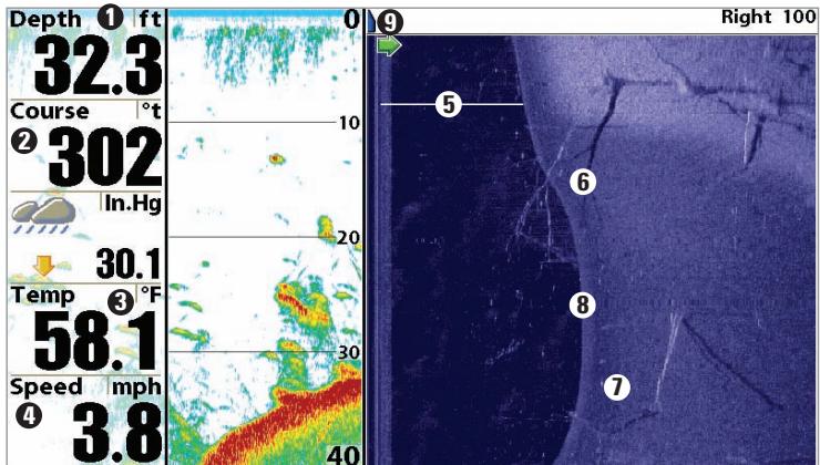
Side/Sonar Combo View
1 Depth
Course: Bearing of Boat with Respect to North Reference
Water Surface Temperature
Speed
Water Column
Shadows 6
Topography Changes 7
Bottom Return 8
Boat Icon 9
Snapshot and Recording View
Snapshot and Recording View displays and allows you to view both screen snapshot thumbnails and recording icons captured to an optional-purchase MMC/SD card installed in your unit. In addition, when you are in the Snapshot and Recording View, Start Recording, Stop Recording, Delete Image, Delete All Images, Delete Recording, Delete All Recordings, Pings Per Second, Playback Speed and Stop Playback are added to the X-Press™ menu.
The Snapshot and Recording View displays up to three screen snapshot thumbnails or recording icons on the screen at a time; you may have to scroll using the 4-WAY Cursor keys to see the whole list of thumbnails and/or icons in this view. The selected thumbnail or icon will be highlighted with arrows.
NOTE: The speed of the screen capture or of the recording depends on the type of card you use; in general, SD cards capture the screen faster than MMC cards do.
Snapshot and Recording View
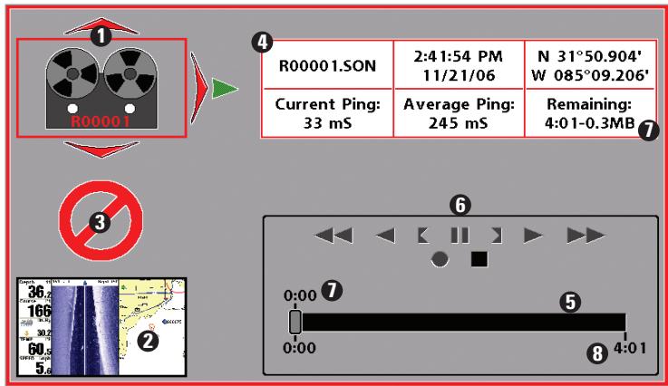
1 Recording icon Amount of recording left to play 5
2 Snapshot thumbnail Recording mode icons 6
3 Unavailable icon Amount of recording that has been played 7
Information box Amount of space used for this recording 8
NOTE: For snapshots and recordings, the indicator bar has several states: during recording, the amount of space remaining on the MMC/SD card is indicated on the status bar. During playback, the amount of time/memory remaining to play is indicated on the status bar. When a snapshot thumbnail is highlighted, the amount of room remaining on the MMC/SD card is indicated.
Screen Snapshot: When Screen Snapshot is enabled (from the Accessories menu tab), pressing the MARK key creates a saved screen capture (when you have an optional-purchase MMC/SD card installed). Once you have created a screen capture, a screen capture thumbnail is added to the Snapshot and Recording View, and is available to view at a later date. See the full-sized image by highlighting a thumbnail (using the Up or Down 4-Way Cursor keys), then using the Right 4-Way Cursor key to view the full image. A border around the full-size screen snapshot indicates that it is just a screen snapshot, not a "live" view. You can delete the selected image, or all images, by selecting a thumbnail and using Delete Image, or using Delete All Images from the Snapshot and Recording X-Press™ menu.
Working with screen snapshots is a four-step process:
- Enabling Screen Snapshot from the Accessories Menu.
- Making a Screen Snapshot using the MARK key.
- Viewing a Screen Snapshot using the Snapshot and Recording View.
- Deleting a Screen Snapshot using the Snapshot and Recording X-Press™ menu.
For more information, see Accessories Menu Tab: Using Screen Snapshot and Snapshot and Recording X-Press™ Menu.
When you start a screen snapshot, you will see a message that a waypoint has been created at the point where your cursor is on the screen, and the screen will freeze while the snapshot is being saved to the MMC/SD card. A status dialog box will appear that shows the progress of the save as a percentage, and that displays the numbered file name assigned to the .BMP file that is being created. Snapshot filenames begin with the letter "S". For more information, see Accessories Menu Tab: Using Screen Snapshot procedure and Snapshot and Recording X-Press™ Menu.
Recording and Playback: From the Snapshot and Recording View, you can use the X-Press™ menu to start and stop recording, and to change the pings per second (which alters the detail level of the recording). Once you are recording already, playing back a recording and screen snapshot viewing are not allowed, and the only Sonar Recording menu choices available in the X-Press™ menu are Stop Recording and Pings Per Second. Use the 4-WAY Cursor keys from the Snapshot and Recording View to start playback of a specific recording icon. You can then cycle through all the views using the VIEW key to see what those views looked like during the recorded time period. You can also use the X-Press™ menu to change playback speed, stop playback, and delete recording icons.
Working with sonar recordings is a six-step process:
- Displaying the Snapshot and Recording View.
- Starting a sonar recording using the Snapshot and Recording X-PressTM menu.
-
Changing the maximum ping rate for the recording using the Snapshot and Recording X-Press™ menu (optional).
-
Stopping a recording using the Snapshot and Recording X-Press™ menu.
- Playing back a recording, using the Snapshot and Recording View and the 4-Way Cursor keys, and changing the playback speed using the Snapshot and Recording X-Press™ menu.
- Deleting a recording using the Snapshot and Recording X-Press™ menu.
For more information, see Snapshot and Recording X-Press™ Menu.
When you start a sonar recording, you will see a message that a waypoint has been created at your current location. During recording, playing back a recording and screen snapshot viewing are not allowed. An information box displays a variety of information including the numbered file name assigned to the .SON file that is being created. The slider bar at the bottom of the screen shows the progress of the recording as well as how much space is remaining on the MMC/SD card.
NOTE: The waypoints that are created by a recording have the same name as the file and use a custom waypoint icon. Recording filenames begin with the letter "R".
For more information, see Snapshot and Recording X-Press™ Menu.
Recording Slider Bar
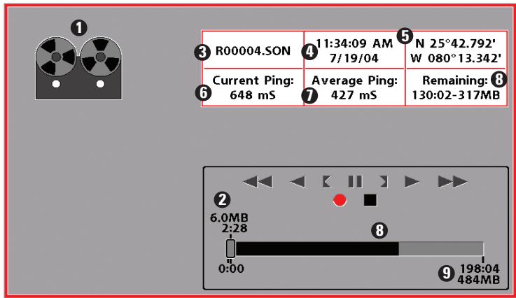
1 Recording Indicator Current Ping Rate 6
2 Amount of space and time used by this recording Average Ping Rate 7
3 Name of recording Amount of space remaining on card 8
Time and Date recording was started Total amount of space on card 9
Position where recording was started
Highlighting a recording: You can scroll through the whole list of recording icons available in the Snapshot and Recording View using the 4-WAY Cursor keys. The highlighted icon will be surrounded by arrows, and a green play triangle will appear to its right.
Playing back a recording: Highlight a recording icon (using the Up or Down 4-Way Cursor keys), then use the Right 4-Way Cursor key to start playback. During playback, all active navigation is cancelled, all other thumbnails and icons will disappear, and a "Playback" message box similar to the Simulation message will be displayed periodically. When playback begins, the view is automatically switched to the primary Sonar View for your model, and no live sonar data will be displayed; only recorded sonar and GPS data will be shown, and the Snapshot and Recording View will display the playback status. You can change the speed, skip to the beginning or end of playback, and even reverse playback, using the Playback Speed X-Press™ menu item, and stop the playback using the Stop Playback X-Press™ menu item; these items are added to the X-Press™ menus in all views during playback. In the Snapshot and Recording View only, playback speed can also be changed using the Left and Right 4-Way Cursor keys. Playback is paused when the sonar cursor is active and resumes playing when the cursor is removed. Playback is automatically paused when the end of the recording is reached.
NOTE: Sonar chart speed is increased during Fast Forward and reversed during Rewind. This may reduce the quality of the sonar image, since at higher speeds, not every sonar return can be processed and displayed.
NOTE: Navigation is not affected by the Sonar Recording feature, but any active navigation is cancelled when playback begins or ends.
Recording Playback
| R00099.SON | 4:58:26 PM 3 12/01/06 | N 31°50.479' W 085°09.018' |
| Current Ping: 54 mS | Average Ping: 197 mS | Remaining: 6:11 |
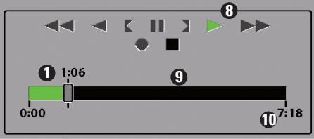
Amount of time already played
2 Name of recording
Time and Date recording started
4 Position when recording started
Current playback ping rate
Average ping rate 6
Amount of time remaining to play 7
Playback speed icons 8
Amount of time remaining to play 9
Overall length of recording 10
You can delete the highlighted recording, or all recordings, using Delete Recording or Delete All Recordings from the Snapshot and Recording X-Press™ menu.
Side Beam View
(only with optional-purchase QuadraBeam PLUS™ transducer)
Side Beam View is only available if you have connected a QuadBeam™ transducer accessory and when Transducer Select is set to QuadBeam (see Sonar Menu Tab: Transducer Select). This view shows sonar information from both the left and right 455 kHz beams and the 200 kHz down-looking beam in one view. You can customize the way the sonar data is displayed in the Side Beam View to suit your personal preferences. Depending on the layout selected from the Quad Layout Sonar X-Press™ menu (only available on the Sonar X-Press™ menu when in Side Beam View), the display will represent the same sonar data in one of the following three layouts: Default, Classic, and Slanted.
Default layout: The top portion of the display presents a historical log of sonar returns from the 200 kHz down-looking sonar beam. New information in the down beam panel scrolls from right to left. The bottom portion of the display presents a historical log of sonar returns from the 455 kHz right- and left-looking sonar beams. New information in the side beam panels scrolls from the center out.
Side Beam View, Default Layout
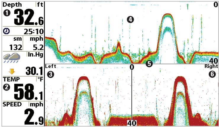
0 Depth
Temperature
Left Side 455 kHz Sonar History Window
200 kHz Sonar History Window
Water Surface Line for 455 kHz Sonar History Windows
Right Side 455 kHz Sonar History Window
Classic layout: The top portion of the display presents a historical log of sonar returns from the 200kHz down-looking sonar beam. New information in the down beam panel scrolls from right to left. The bottom portion of the display presents a historical log of sonar returns from the 455kHz right- and left-looking sonar beams. New information appears at the top, and scrolls down the display.
Side Beam View, Classic Layout
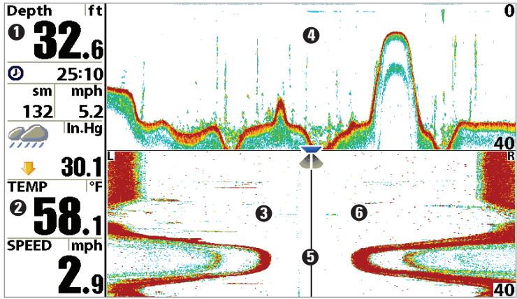
1 Depth
Temperature
Left Side 455 kHz Sonar History Window
200 kHz Sonar History Window
Water Surface Line for 455 kHz Sonar History Windows
Right Side 455 kHz Sonar History Window
Slanted layout: This layout presents the two 455 kHz side sonar beams and the 200 kHz down-looking sonar beam as three panels of historical data. This layout is presented as three slanted panels. New information appears on the right, and scrolls to the left.
Side Beam View, Slanted Layout
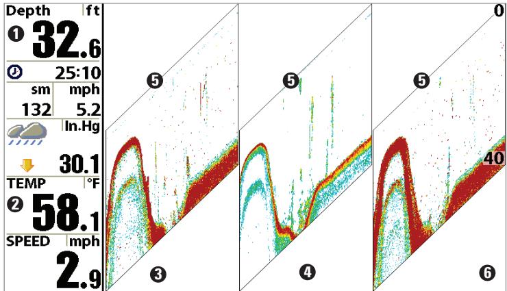
1 Depth
2 Temperature
3 Left Side 455 kHz Sonar History Window
200 kHz Sonar History Window 4
Water Surface Line for 455 kHz Sonar History Windows
Right Side 455 kHz Sonar History Window
In all of these layouts, the sonar information from the side-looking beams reveals bottom contour, structure and fish similar to the down-looking beam, but the area covered is to the left and right of the area shown in the down-looking portion, so you actually see more of the bottom. The distance covered by the right and left beams is based on the depth setting for the down-looking beam, up to a maximum of 160 feet.
Bird's Eye View
Bird's Eye View shows a 3D perspective view of the track and the chart land contour from a point above and behind the boat (the eye point). As the boat turns, the eye point moves to follow the boat. Big Digits on this view provide digital data in a large, easy-to-see format.
When you press the 4-WAY Cursor key in the Bird's Eye View, the position of the eye point will shift. This allows you to move and turn the eye point so that you can look off to the sides, or even behind the boat. Pressing the RIGHT or LEFT arrow keys on the 4-WAY Cursor key turns the eye point right or left, while pressing the UP arrow key moves the eye point forward, and pressing the DOWN arrow key moves the eye point backward.
Pressing the EXIT key moves the eye point back to its original position behind and above the boat.
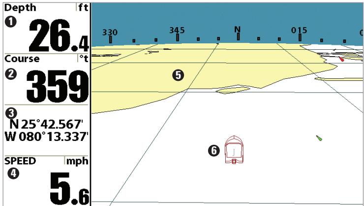
Bird's Eye View
1 Depth
Course: Direction that boat is travelling relative to North Reference
3 Latitude and Longitude Position of Boat
Speed of Boat 4
Land Contours 5
Boat Icon
Chart/Bird's Eye Combo View
Chart/Bird's Eye Combo View shows both the Chart and Bird's Eye views in a combination split screen. You can perform any of the functions for either of these views, but only when the view you want to control is selected as the active side (see Sonar X-Press™ Menu: Active Side or Navigation X-Press™ Menu: Active Side for more information). A green arrow points to the side that is active. You can also adjust the size of the left side of a split screen (see Sonar X-Press™ Menu: Split Position or Navigation X-Press™ Menu: Split Position for more information).
NOTE: See Bird's Eye View and Chart View for more information about each side of this view.
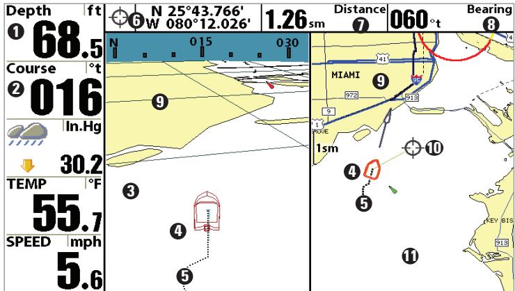
Chart/Bird's Eye Combo View
1 Depth Latitude and Longitude Position of Cursor 6
Course: Direction that boat is travelling Distance to the Cursor 1
relative to North Reference
3 Bird's Eye Window
4 Boat Icon
Track (Breadcrumb Trail)
Bearing to the Cursor 8
Cartography 9
Active Cursor
Chart Window 1
Chart/Chart Combo View
Chart/Chart Combo View shows two versions of the Chart view in a combination split screen, so that you can see the position of the boat on one side while you zoom in or perform other functions on the other. You can perform any of the functions for the Chart view, but only on the side of the view you have selected as the active side (see Sonar X-Press™ Menu: Active Side or Navigation X-Press™ Menu: Active Side for more information). A green arrow points to the side that is active. You can also adjust the size of the left side of a split screen (see Sonar X-Press™ Menu: Split Position or Navigation X-Press™ Menu: Split Position for more information).
NOTE: See Chart View for more information about each side of this view.
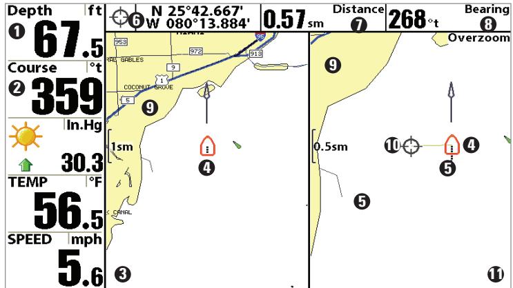
Chart/Chart Combo View
Depth Latitude and Longitude Position of Cursor 6
Course: Direction that boat is travelling Distance to the Cursor 1
relative to North Reference
Chart Window 1
Boat /conn 1
Track/Breadcrumb Trail
Chart Window 2 ①
Chart View
Chart View shows cartography from the built-in UniMap™ or an optional MMC/SD map for the area surrounding your current position. The current track (also known as the position history or breadcrumb trail) showing where the boat has been, along with saved tracks, waypoints, and the current route (when navigating), are overlaid on the chart. You can use the 4-WAY Cursor Control key to shift/pan the chart to another area. You can use the ZOOM (+/-) keys to zoom in and out. You can use the INFO key to get information on the chart objects near the cursor.
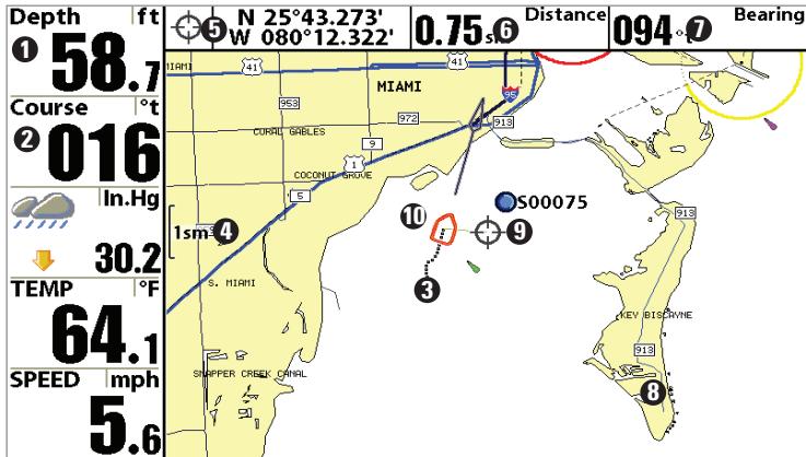
Chart View with Active Cursor
1 Depth Distance to the Cursor 6
2 Course: Direction that boat is travelling Bearing to Cursor 7
relative to North Reference. Track (Readcrumb Trail) Cartography 8
Active Cursor 9
Wbp Scale Latitude and Longitude Position of Cursor Boat Icon
Chart/Sonar Combo View
Chart/Sonar Combo View shows both the Chart and Sonar views in a combination split screen. You can perform any of the functions for either of these views, but only when the view you want to control is selected as the active side (see Sonar X-Press™ Menu: Active Side or Navigation X-Press™ Menu: Active Side for more information). A green arrow points to the side that is active. You can also adjust the size of the left side of a split screen (see Sonar X-Press™ Menu: Split Position or Navigation X-Press™ Menu: Split Position for more information).
NOTE: See Sonar View and Chart View for more information about each side of this view.
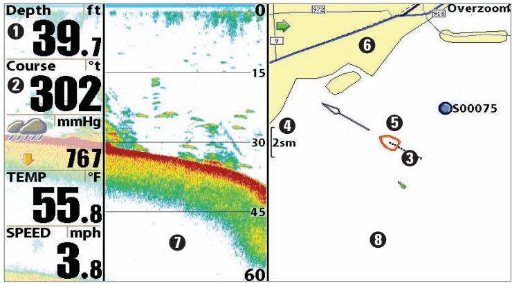
Chart/Sonar Combo View
1 Depth Boat Icon 5
2 Course: Direction that boat is travelling Carotgraphy 6
relative to North Reference
3 Track (Breadcrumb Trail)
A Man Scale Chart Window 8
Chart/Side Combo View
Chart/Side Combo View shows regular chart information and side imaging sonar information in a combination split screen. You can perform any of the functions for either of these views, but only when the view you want to control is selected as the active side (see Navigation X-Press™ Menu: Active Side or Side Imaging X-Press™ Menu: Active Side for more information). A green arrow points to the side that is active. You can also adjust the size of the left side of a split screen (see Navigation X-Press™ Menu: Split Position or Side Imaging X-Press™ Menu: Split Position for more information).
NOTE: See Side Imaging View and Chart View for more information about each side of this view.
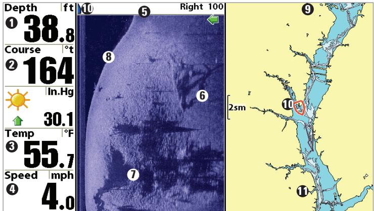
Chart/Side Combo View
1 Depth
Course: Bearing of Boat with Respect to North Reference
Water Surface Temperature
4 Speed of Boat
Side View Window
6 Shadows
Topography Changes 7
Bottom Return 8
Chart View Window 9
Boat Icon 10
Cartography 1
Chart Orientation
All the chart views allow you to choose the orientation of the chart. When North-Up orientation is selected, True North is shown at the top of the display. In other words, objects located to the north of the boat are drawn above the boat. When Course-Up orientation is selected, the direction of motion of the boat is shown at the top of the display. In other words, objects ahead of the boat are drawn above the boat. In both orientations, the view pans automatically, so that the boat is always centered on the display. When the boat is stationary, it is drawn as a circle. When the boat is in motion, it takes on a boat shape, pointed in the direction of motion (always Up in the Course-Up orientation). See Navigation Menu Tab: Chart Orientation for more information.
Viewing Cartography
In the Chart or Combo Views, there are several cartography-related functions that you can access using various keys.
Panning: Use the 4-WAY Cursor keys to move the chart around on the display in the direction of the key being pressed. When you do this, a Bullseye Cursor is drawn at the top of the screen and is linked to the boat by a yellow line, even if the boat is off the screen. At the same time, a cursor dialog box is displayed at the top of the screen with the distance and bearing from the boat to the cursor position and the latitude/longitude coordinates of the cursor. When the cursor is active on the display, you can also use the 4-WAY Cursor Control key to move the cursor diagonally.
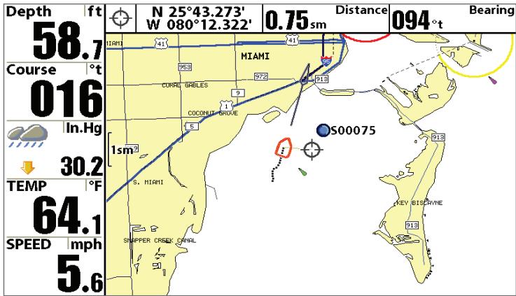
Chart View with Cursor Present
Zooming: Use the Plus (+) key to Zoom In and the Minus (-) key to Zoom Out showing the cartography at different scales. The scale is indicated on the left side of the display. If you zoom in beyond the available chart data, the display will go into Overzoom mode whereby the last available chart data is amplified to reflect the scale selected. If you zoom in so far that no cartography is available, a lat/lon grid will be drawn instead.
Chart Info: Use the INFO key to get detailed information about the chart. If the cursor is active, you will see information about the chart objects located near the cursor. If the cursor is not active, the Chart Info menu will appear. You can select the nearest port, the nearest tide station, or the nearest current station to see information about any of these objects.
NOTE: The built-in UniMap™ does not contain any Port, Tide or Current information. This information is only available from optional-purchase MMC/SD cards.
Nearest Port: The position and services information for the nearest port to your present position will be displayed. Press the EXIT key to remove the information box and the Bullseye Cursor will be centered over the port position. The Cursor Information Boxes will indicate the distance and bearing to the port from your present position.
Nearest Tide Station: Tide information for the nearest tide station to your present position will be displayed. This includes the position of the station and the times of the high and low tides for today's date. A tide graph is also displayed showing the rise and fall of the tides for the 24 hour time period encompassing the date. You can change the date to look at tide information before or after the date displayed by pressing the LEFT or RIGHT Cursor key respectively. Press the EXIT key to remove the information box and the Bullseye Cursor will be centered over the tide station position. The cursor information boxes will indicate the distance and bearing to the tide station from your present position.
Nearest Current Station: Current information for the nearest current station to your present position will be displayed. This includes the position of the station and the current changes for today. Two graphs are also presented that show the time, direction and flow speed of the current changes for the 24 hour time period of today's date. You can change the date to look at current information before or after the date displayed by pressing the LEFT or RIGHT Cursor key respectively. Press the EXIT key to remove the information box and the Bullseye Cursor will be centered over the current station position. The Cursor Information Boxes will indicate the distance and bearing to the current station from your present position.
Navigation
Use the 900 Series™ to establish waypoints at areas of interest and to navigate to those waypoints via a saveable route (representing the shortest intended distance between waypoints). You can also view and save tracks, which represent the actual path of the boat.
Waypoints, Routes and Tracks
Waypoints are stored positions that allow you to mark areas of interest or navigation points. Your 900 Series™ can store up to 3000 waypoints.
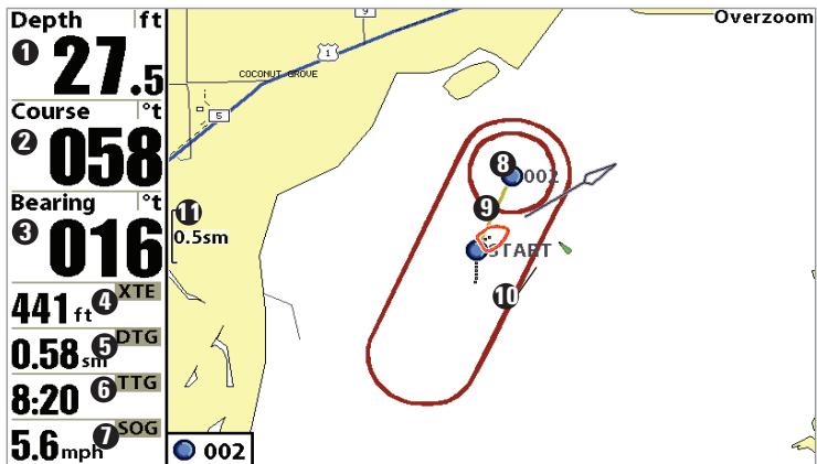
Waypoints, Routes and Tracks

Depth

Course: Direction that boat is traveling relative to North Reference

Bearing: Direction to Destination Waypoint Relative to North Reference

XTE: Cross Track Error. Distance of Boat from Route

DTG: Distance to Go to Waypoint
TTG: Estimate of Trip Time to Destination Waypoint
Speed Over Ground: Speed of Boat
Waypoint
Route
Off-Course Alarm Limits
Map Scale
Routes link two or more waypoints together to create a path for navigation, and are used in trip planning. You can link individual waypoints together by using the GOTO key. A route represents your intended navigation and shows the shortest path from each waypoint to the next. As you travel a route, staying on the route line is the most efficient way to get to your destination, although you should always look out for obstacles not shown on the chart. Your 900 Series™ can store up to 50 routes that can each contain up to 50 waypoints.
Tracks consist of detailed position history, and are displayed as a breadcrumb trail of trackpoints. The Current Track shows the position history since the unit was powered up (maximum of 20,000 trackpoints displayed). You can clear the Current Track or save it at any time. Your 900 Series™ can store up to 50 saved tracks, each containing 20,000 trackpoints. The current track represents your actual path so far.
Save, Edit, or Delete a Waypoint
Save your current position as a waypoint: On any view, press the MARK key to save the current position of the boat as a waypoint.
Save the cursor position as a waypoint: On the Chart or Combo view, use the Cursor key to designate the position you want to save as a waypoint. Then press the MARK key to save the marked position as a waypoint.
Save a position from the sonar history: Use the Cursor key to point to a feature in the sonar history (also called the Sonar Saver feature). Press the MARK key to create a waypoint at the location where that sonar reading was taken. The new waypoint will also record the depth at that location.
NOTE: When you save a waypoint by any of these methods, a numerical waypoint name is automatically assigned. You can edit the waypoint information later to give it a different name and select an icon to represent it (see Waypoint submenu on the Navigation Main Menu Tab).
Display the Waypoints Submenu: From any view, press the MENU key twice to display the Main Menu System, then use the RIGHT Cursor key to select the Navigation tab. Select Waypoints and press the RIGHT Cursor key to display the Waypoints submenu.
Program a specific position as a waypoint: To create a waypoint that is NOT your current position, from the Waypoints submenu, select the Create option and press the RIGHT Cursor key. Use the Cursor keys to program a waypoint name, latitude, longitude, and icon before selecting Save.
Edit a waypoint: From the Waypoints submenu, select Edit and press the RIGHT Cursor key to display a list of saved waypoints. Select the waypoint you want to edit and press the RIGHT Cursor key. Use the 4-WAY Cursor Control key to move from field to field, and the UP and DOWN Cursor keys to changes values once you are in a field. In the Waypoint Name, Latitude and Longitude fields, use the UP and DOWN Cursor keys to change the letter or number. All upper and lower case letters are available, as well as digits 0-9 and some punctuation characters. In the Waypoint Icon field, use the UP and DOWN Cursor keys to change the icon used to represent the waypoint on the Combo and Chart Views. You can exit these fields with the LEFT and RIGHT Cursor keys or by pressing the EXIT key. Select Save and press the RIGHT Cursor key to save your changes.
To make it easier to select a waypoint, select Sort By and press the RIGHT or LEFT Cursor keys to select a sort order:
- Name shows the waypoints alphabetically
- Time shows the most recently-created waypoint first
- Distance shows the closest waypoint first.
Delete a waypoint: From the Waypoints menu, select Delete and press the RIGHT Cursor key to display a list of waypoints. Select the waypoint you want to delete, then press the RIGHT Cursor key. You will be asked to confirm deletion before the waypoint is actually deleted.
Navigate to a Waypoint or Position
Navigate to the cursor position: From any Chart or Combo view, use the Cursor key to select a position or waypoint to which you want to navigate. Press the GOTO key. Navigation will begin immediately.
Navigate to a specified waypoint: Press the GOTO key, then choose the waypoint to which you would like to navigate from the waypoint list and press the RIGHT Cursor key to select it.
NOTE: By repeating the previous instructions, you can add more waypoints to create a longer multi-segment route.
Skipping a waypoint: From the Navigation X-Press™ Menu, select Skip Next Waypoint and press the RIGHT Cursor key. If there is not another waypoint to skip to, navigation will be cancelled.
Cancel navigation: From the Navigation X-Press™ Menu, select Cancel Navigation and press the RIGHT Cursor key. Canceling navigation removes the route and any waypoints created using the GOTO key, but does not remove any saved routes from memory. You will be prompted to save the current route when you cancel navigation.
Add a Waypoint Target or Trolling Grid
Add or Remove a Waypoint Target: From the Waypoints submenu (accessed from the Navigation main menu), select Target and press the RIGHT Cursor key to display a list of waypoints. Select the waypoint you want to target. A target consisting of concentric circles centered on the selected waypoint will appear on all of the navigation views; the target shows various distance ranges from the targeted waypoint. To remove the target, choose Remove Target from the Navigation X-Press™ Menu.
NOTE: Only one waypoint can have either a target or a grid at one time. If you apply a target or a grid to a new waypoint, the original waypoint will lose its target or grid.
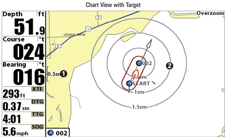
Map Scale
Waypoint Target 2
Add or Remove a Trolling Grid: From the Waypoints menu (accessed from the Navigation main menu), select Grid and press the RIGHT Cursor key to display a list of waypoints. Select the waypoint to which you want to add the grid. The trolling grid will appear on all of the navigation views, and can be used as a guide when trolling around a waypoint. The grid can be rotated to any desired heading using Grid Rotation from the Navigation Main menu. To remove the trolling grid, choose Remove Grid from the Navigation X-Press™ Menu.
Chart View with Grid
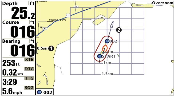
Map Scale
WaypointTrollingGrid 2
NOTE: Only one waypoint can have either a target or a grid at one time. If you apply a target or a grid to a new waypoint, the original waypoint will lose its target or grid.
NOTE: The spacing of the rings on the waypoint target and the spacing of the grid lines on the trolling grid is the same as the length of the scale bar on the left edge of the display. Zooming in or out will decrease or increase the spacing, respectively.
Save, Edit or Delete a Route
Save the current route: While you are navigating, the current route can be saved. From the Navigation X-Press™ Menu, select Save Current Route and press the RIGHT Cursor key. Navigation will continue.
Display the Routes menu: From any view, press the MENU key twice to display the Main Menu System, then use the RIGHT Cursor key to select the Navigation tab. Select Routes and press the RIGHT Cursor key to display the Routes menu.
Create a route: From the Routes submenu, select Create and press the RIGHT Cursor key. A Route Edit screen will be displayed with an empty route. You can name the route, add waypoints to the route from the list of all waypoints, and order the waypoints in the route using the Cursor keys.
Edit a saved route: From the Routes submenu, select Edit and press the RIGHT Cursor key. A Route Edit screen will be displayed. Select the route you wish to edit and press the RIGHT Cursor key. Re-name the route or change, delete or re-order the waypoints used in the route.
Delete a saved route: From the Routes submenu, select Delete and press the RIGHT Cursor key. Select the route you wish to delete and press the RIGHT Cursor key. You will be asked to confirm your choice by pressing the RIGHT Cursor key again before the route is deleted.
Travel a saved route: From the Routes submenu, select Travel and press the RIGHT Cursor key. A list of saved routes will appear. Select the route you wish to travel and press the RIGHT Cursor key to make this route the current route and begin navigation. You may also travel the route in either forward or reverse order.
Route Info: From the Routes submenu, select Info and press the RIGHT Cursor key. A list of saved routes will appear. Select the route for which you want information, and press the RIGHT Cursor key. The list of waypoints in the route will be shown, with the distance and bearing from each waypoint to the next, as well as the distance and bearing from the current position to the first waypoint in the route.
Save or Clear a Current Track
Save the current track: From the Navigation X-Press™ Menu, select Save Current Track and press the RIGHT Cursor key. The track will remain on the display, but will change from black to gray. To remove the track completely from the display, see Edit, Delete or Hide Saved Tracks.
NOTE: When you save a track, a name is automatically assigned. The track name consists of a date/time stamp, but can be re-named later (see Edit, Delete, or Hide Saved Tracks).
Clear the current track: From the Navigation X-Press™ Menu, select Clear Current Track and press the RIGHT Cursor key. The track will be removed from the display and discarded.
Edit, Delete or Hide Saved Tracks
Display the Tracks Submenu: From any view, press the MENU key twice to display the Main Menu System, then use the RIGHT Cursor key to select the Navigation tab. Select Tracks and press the RIGHT Cursor key to display the Tracks submenu.
Edit a saved track: From the Tracks submenu, select Edit and press the RIGHT Cursor key to display the list of saved tracks. Select the track you want to edit and press the RIGHT Cursor key. When the Edit Track dialog box appears, use the Cursor keys to move between fields. In the Track Name field, the UP and DOWN Cursor keys change the letter or number. All upper and lower case letters are available, as well as digits 0-9 and some punctuation characters. You can exit the Track Name field with the LEFT and RIGHT Cursor keys or by pressing the EXIT key. Select Save and press the RIGHT Cursor key to save your changes.
Delete a saved track: From the Tracks submenu, select Delete and press the RIGHT Cursor key to display the list of saved tracks. Select the track you want to delete and press the RIGHT Cursor key. You will be asked to confirm deletion before the track is actually deleted.
Hide or display a saved track: From the Tracks submenu, select Visibility and press the RIGHT Cursor key to display the list of saved tracks. Select the track you want to hide or display and use the Cursor keys to select Hidden or Visible. Press the EXIT key to return to the Tracks submenu.
Man Overboard (MOB) Navigation
As soon as you know that you have a man overboard, you should activate MOB navigation to maximize chances for a successful rescue. MOB navigation allows you create an MOB waypoint to locate the point at which your man went overboard, and the relation of the boat to that point. When MOB is activated, an MOB waypoint, which is a permanent, sharable waypoint with a large, distinctive icon, is created at the boat's current position (regardless of whether the chart cursor is active or not). Any current navigation will be cancelled and the current route discarded without user notification, and MOB navigation will begin immediately. A line will be drawn from the boat's current position to the MOB waypoint, and the MOB waypoint will be targeted. The view is switched to the Chart View automatically when MOB is activated, and an additional info box that shows the lat/lon position of the MOB waypoint and the elapsed time since MOB was activated is added to the Chart View.
It is not possible to re-activate MOB or modify the current route without first canceling MOB navigation. The Off Course trigger is also disabled and the Off Course Alarm circle is not drawn. Any press of the GOTO key, or selection of a GOTO menu item, will cause an error beep and a short message will be displayed to the user that will disappear after 2 seconds.
Activate MOB navigation: Press and hold the GOTO key for more than 1.5 seconds to activate the Man Overboard (MOB) function.
Cancel MOB navigation: From the Navigation X-Press™ menu, select Cancel MOB and press the RIGHT Cursor key. Canceling MOB navigation removes the route and any waypoints created using the GOTO key, but does not remove any saved routes from memory.
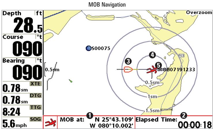
Position where man fell overboard
2 Elapsed time since MOB was activated
3 Boat icon
Target surrounding MOB waypoint 4
MOB waypoint 5
The Menu System
The menu system is divided into easy-to-use menu modules. The main components of the menu system are:
Start-Up Options Menu: Press the MENU key during the power up sequence to view the Start-Up Options menu. See Start-Up Options Menu.

X-PressTM Menu
X-PressTM Menu: The X-PressTM Menu allows you to access the settings that are changed frequently without having to navigate through the whole menu system. Press the MENU key once to display the X-PressTM Menu. When you select a menu item from the X-PressTM Menu, the menu will collapse, leaving only the menu choice on the screen. Use the UP or DOWN Cursor keys to reactivate the X-PressTM Menu.
NOTE: The X-Press™ Menu choices will vary depending on which view is active when you press the MENU key, as well as whether you are in Normal or Advanced User Mode. Either the Sonar or Navigation X-Press™ Menu will appear, depending on the view you are in.
Main Menu Tabs: Less frequently-adjusted menus are grouped into the Main Menu System. The Main Menu system is organized under main tab menu headings to help you find a specific menu item quickly. Main tab headings are: Alarms, Sonar, Navigation, Chart, Setup, Views, and Accessories.
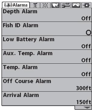
Main Menu System Normal User Mode
Press the MENU key twice for the Main Menu, then use the 4-WAY Cursor LEFT or RIGHT key to select a tab, and use the DOWN or UP key to select a specific menu item under that tab, then use the LEFT or RIGHT keys again to change a menu setting. Press the EXIT key to move quickly to the top of the tab. A down arrow at the bottom of a menu means that you can scroll to additional menu choices using the DOWN Cursor key. A right or left arrow on a menu choice means that you can use the RIGHT or LEFT Cursor keys to make changes or to see more information.
NOTE: The Main Menu choices will vary depending on whether you are in Normal or Advanced User Mode, and what model you own.
User Mode (Normal or Advanced): An Advanced Mode is provided for users who desire the highest level of control over the 900 Series™ and Normal Mode for users who desire greater simplicity and fewer menu choices. Additional Advanced menu choices will be displayed throughout the menu system when you navigate to specific menus while in Advanced Mode. Any changes made while in Advanced Mode will remain in effect after you switch back to Normal Mode. See Setup Menu Tab: User Mode for specific instructions on changing to the User Mode.
NOTE: The 900 Series™ defaults to Advanced User Mode on start-up.
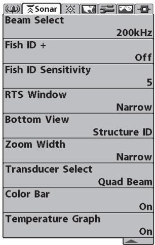
Sonar Tab, Normal Mode
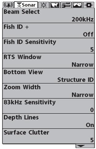
Sonar Tab, Advanced Mode
Total Screen Update: when you change any menu settings that affect the Sonar View, the view will update immediately (i.e. you don't have to exit the menu to apply the change to the screen).
Start-Up Options Menu
Press the MENU key when the Title screen is displayed to access the Start-Up Options menu.
Start-Up Options Menu
Start-Up Options
Normal
Simulator
System Status

Press Right Cursor Arrow to Select
Transducer not connected
Use the UP or DOWN 4-WAY Cursor keys to position the cursor, then the RIGHT Cursor key to select one of the following choices. If you wait too long, the system will default to whichever menu mode happens to be highlighted:
Normal
- Simulator
- System Status.
See the following paragraphs for more information about each of these choices.
Normal Operation
Use Normal operation for on-the-water operation with a transducer connected. In addition, your 900 Series™ uses advanced transducer detection methods to determine if a transducer is connected. If a functioning transducer is connected, Normal operation will be selected automatically at power up and your 900 Series™ can be used on the water.
Exit Normal operation by powering your 900 SeriesTM off.
Simulator
Use the Simulator to learn how to use your 900 Series™ before taking your boat on the water. The Simulator is a very powerful tool that simulates on-the-water operation, providing a randomly-updated display. We recommend going through this manual while using the Simulator, since all of the menus function and affect the display the way they actually do when in Normal operation.
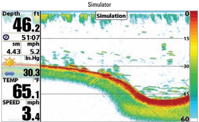
NOTE: To get the full benefit of the Simulator, it is important to select Simulator manually from the Start-Up Options menu as opposed to letting the 900 Series™ enter Simulator automatically (as it will if a transducer is not connected and you do nothing during power up). Manually selecting Simulator from the Start-Up Options menu allows you to pre-configure your 900 Series™ for on-the-water operation. Any menu changes you make will be saved for later use.
A Simulation message will appear on the display periodically to remind you that you are using the Simulator.
Exit the Simulator by powering your 900 SeriesTM off.
System Status
Use System Status to view system connections and to conduct a unit self-test. Exit System Status by powering your 900 Series™ off.
The following screens are displayed in turn when you press the VIEW button when using System Status:
Self Test
- Accessory Test
- GPS Diagnostic View.
Self Test
Self Test displays results from the internal diagnostic self test, including unit serial number, Printed Circuit Board (PCB) serial number, software revision, total hours of operation and the input voltage.
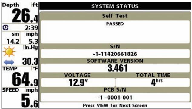
Self Test Screen
Accessory Test
Accessory Test lists the accessories connected to the system.
Accessory Test Screen
| Depth ft 26.6 | SYSTEM STATUS | ||
| ACCESSORY TEST | |||
| CannonLink | CONNECTED | ||
| GPS | CONNECTED | ||
| SmartCast WSL | CONNECTED | ||
| Speed | CONNECTED | ||
| Temperature | CONNECTED | ||
| WeatherSense | CONNECTED | ||
| ① | 2:39 | ||
| sm | mph | ||
| 14.2 | 5.3 | ||
| In.Hg | 30.3 | ||
| TEMP | °F | ||
| 63.7 | |||
| SPEED | mph | ||
| 5.6 | |||
NOTE: The speed accessory will be detected only if the paddlewheel has moved since your 900 Series™ was powered up.
GPS Diagnostic View
GPS Diagnostic View, which is only available when a GPS Receiver is attached to you 900 Series, shows a sky chart and numerical data from the GPS receiver. The sky chart shows the location of each visible GPS satellite with its satellite number and a signal strength bar. A dark grey bar indicates that the satellite is being used to determine your current position. A light gray bar indicates that the satellite is being monitored, but is not yet being used.
This view also reports the current position, local time and date, and other numeric information. The current GPS Fix Type is reported as No Fix, 2D Fix, 3D Fix, or Enhanced. An Enhanced fix has been augmented using information from WAAS, EGNOS, or MSAS. A 3D or Enhanced Fix is required for navigation. HDOP (the Horizontal Dilution of Precision) is a GPS system parameter which depends on the current satellite configuration. HDOP is used to calculate the Estimated Position Error.
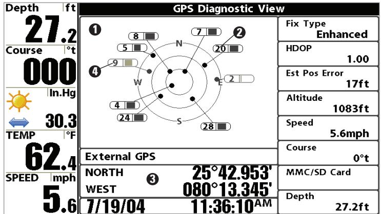
GPS Diagnostic View
SkyChart
±b2 Satellite Being Used
Current Latitude and Longitude
Satellite Being Monitored
3
4
| Active Side Left |
| Split Position 50 |
| Sensitivity 10 |
| Upper Range 0ft |
| Lower Range Auto |
| Chart Speed 5 |
| Quad Layout Default |
| Bottom Lock Off |
| Bottom Range 15ft |
| Sonar Colors Standard |
| Cancel Navigation |
Sonar X-PressTM Menu
Sonar X-PressTM Menu
The Sonar X-PressTM Menu provides access to the settings most frequently used. Press the MENU key once while in any of the Sonar Views to access the Sonar X-PressTM Menu.
NOTE: Menu choices will vary depending on system settings such as whether the unit is set for Advanced User mode.
NOTE: Quad Layout only appears in Side Beam View when the optional-purchase QuadraBeam PLUSTM transducer is attached and selected.

Active Side
Active Side allows you to select which side
of a Combo View will be active; key presses will only affect the active side of the screen. When a menu is displayed, the non-active side of the screen will be grayed out; at any other time, a green arrow will point to the active side. Combo Views usually display sonar on the left, with charts or Bird's Eye usually on the right. The Active Side menu choice is only available when a Combo View is active.
To select the Active Side:
- Highlight Active Side on the Sonar X-Press™ Menu.
- Use the RIGHT 4-WAY Cursor Control key to change which side is active. (Left, Right, Default = Left, or Sonar).
Split Position allows you to adjust what
percentage of the screen is taken up by the left side of any Combo View, each view may be adjusted independently; you must be in a specific view to adjust the screen size for that view. The number setting indicates the percentage taken up by the left side of the Combo View; selecting Left sets the left side of the screen to its smallest setting. The Split Position menu choice is only available when a Combo View is active.
To Adjust Split Screen Position
- Highlight Split Position on the Sonar X-Press™ Menu.
- Use the RIGHT 4-WAY Cursor Control key to change the size of the left side of a Combo View. (Left, 30, 40, 50, 60, 70, Right, Default varies)
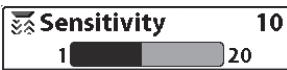
Sensitivity
Sensitivity controls how much detail is shown
on the display. Increasing the sensitivity shows more sonar returns from small baitfish and suspended debris in the water; however, the display may become too cluttered. When operating in very clear water or greater depths, increased sensitivity shows weaker returns that may be of interest. Decreasing the sensitivity eliminates the clutter from the display that is sometimes present in murky or muddy water. If Sensitivity is adjusted too low, the display may not show many sonar returns that could be fish.
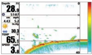
Sensitivity at Low
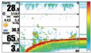
Sensitivity at Medium
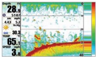
Sensitivity at High
To adjust the Sensitivity:
- Highlight Sensitivity on the Sonar X-PressTM menu.
- Use the LEFT or RIGHT 4-WAY Cursor Control keys to increase or decrease the Sensitivity setting. (Low = 1, High = 20, Default = 10)
Upper Range sets the shallowest depth range that will be displayed on the Sonar, Split Sonar and Active Sonar Side Views. The Upper Range menu choice is available when User Mode is set to Advanced (see Setup Menu Tab:User Mode) and can only be accessed from the Sonar, Split Sonar and Active Sonar Side Views. Upper Range is often used with Lower Range.
For example, if you are only interested in the area between 20 and 50 feet deep, you should set the Upper Depth Range to 20 and the Lower Depth Range to 50. The Sonar View will then show the 30 foot area between 20 and 50, and will not show the surface or the bottom (assuming the bottom is deeper than 50 feet), and will show greater detail for that area between 20 and 50 feet.
NOTE: A minimum distance of 10 feet will be maintained between the Upper and Lower Range regardless of the manual settings entered.
To adjust the Upper Range:
- Make sure you are in Advanced Mode, then highlight Upper Range on the Sonar X-Press™ Menu.
- Use the LEFT or RIGHT 4-WAY Cursor Control keys to increase or decrease the Upper Range setting. (0 to 1490 or 0 to 497 meters [International models only], Default = 0)

Lower Range
Auto
Auto
1500
Lower Range
Lower Range sets the deepest depth range
that will be displayed. Automatic is the default setting. When in automatic mode, the lower range will be adjusted by the unit to follow the bottom. Selecting a specific setting locks the depth range into Manual mode. Use both Upper and Lower Range together to view a specific depth range manually when looking for fish or bottom structure. M will be displayed in the lower right corner of the screen when you start manually adjusting the Lower Range to indicate that you are in Manual mode.
For example, if you are fishing in 60 feet of water but are only interested in the first 30 feet (surface to a depth of 30 feet) you should set the Lower Depth Range limit to 30. The display will show the 0 to 30 foot range, allowing you to see a more detailed view than you would see if the display went all the way to the bottom.
NOTE: A minimum distance of 10 feet will be maintained between the Upper and Lower Range regardless of the settings entered manually.
To adjust the Lower Range:
- Highlight Lower Range on the Sonar X-Press™ Menu.
- Use the LEFT or RIGHT 4-WAY Cursor Control keys to increase or decrease the Lower Range setting. (AUTO, 10 to 1500 feet; 3 to 500 meters [International models only], Default = AUTO)
Chart Speed determines the speed at which
the sonar information moves across the display, and consequently the amount of detail shown. A faster speed shows more information in the Sonar Views and is preferred by most anglers; however, the sonar information moves across the display quickly. A slower speed keeps the information on the display longer, but the bottom and fish details become compressed and may be difficult to interpret. Regardless of the Chart Speed setting, the RTS® Window will update at the maximum rate possible for the depth conditions. Adjust Chart Speed to your personal preference.
To adjust the Chart Speed:
- Highlight Chart Speed on the Sonar X-Press™ Menu.
- Use the LEFT or RIGHT 4-WAY Cursor Control keys to increase or decrease the Chart Speed setting. (1-10, where 1 = Slowest , 10 = Fastest , Default = 5 )
Quad Layout selects the method used to represent the sonar information from the two side-looking beams plus the down-looking beam to be presented on the Side Beam View, and is only available when an optional purchase QuadraBeam PLUS™ transducer is attached and the Side Beam View is active. Use Quad Layout to change the way the Side Beam View is displayed. See Side Beam View for more information.
To adjust the Quad Layout:
- Highlight Quad Layout on the Sonar X-Press™ menu.
- Use the LEFT or RIGHT 4-Way Cursor Control keys to change the Quad Layout setting for the Side Beam View. (Default, Classic, Slanted, Default = Default)

Bottom Lock
(Sonar Zoom View only)
Bottom Lock changes the mode of the Zoomed view in the Sonar Zoom View.
To turn on Bottom Lock:
- In the Sonar Zoom View, highlight Bottom Lock on the Sonar X-Press™ Menu.
- Use the LEFT or RIGHT 4-WAY Cursor Control keys to change the Bottom Lock setting to on. (Off, On, Default = Off).
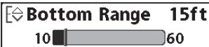
Bottom Range
(Sonar Zoom View only, when Bottom Lock is On)
Bottom Range allows you to control how much of the water column, measured up from the bottom, is shown in the Sonar Zoom View. Choose a small value to see low-lying bottom structure or details of the bottom return. Choose a larger value to see large structure in deeper water. It is possible to set the Bottom Range to be greater than the depth. In this case, you may see surface clutter in a wavy band that mirrors changes in the depth.
To adjust the Bottom Range:
- In the Sonar Zoom View, highlight Bottom Lock on the Sonar X-Press™ Menu.
- Use the LEFT or RIGHT 4-WAY Cursor Control keys to change the Bottom Lock setting to on. (Off, On, Default = Off).
- Once you turn on Bottom Lock, the Bottom Range X-Press™ menu choice will be displayed. (10 - 60 feet or 3-20 meters [International Models only], Default = 15 feet)

Sonar Colors
Sonar Colors allows you to select which
color palette you would like to use for the display.
To change the Sonar Colors:
- Highlight Sonar Colors on the Sonar X-PressTM menu.
- Use the LEFT or RIGHT 4-WAY Cursor Control keys to change the color palette. (Standard, Gray, Inverse, Green, Default = Standard)

Cancel Navigation
(only when Navigating)
Cancel Navigation discards the current route and exits Navigation Mode. This menu choice will only appear when you are currently navigating a route. This will not delete a previously-saved route.
To Cancel Navigation:
- Highlight Cancel Navigation on the Sonar X-Press™ menu.
- Use the RIGHT 4-WAY Cursor Control key to initiate canceling navigation.
- The Confirm dialog box will appear. To cancel navigation, press the RIGHT Cursor key once more. To avoid canceling navigation, press the LEFT Cursor key.
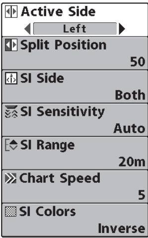
Side Imaging X-PressTM Menu
Side Imaging X-Press™ Menu
(Side Imaging Views only)
The Side Imaging X-Press™ Menu provides access to the settings most frequently-used. Press the MENU key once while in any of the Sonar Views to access the Side Imaging X-Press™ Menu.
Active Side
Active Side allows you to select which side
of a Combo View will be active; key presses will only affect the active side of the screen. When a menu is displayed, the non-active side of the screen will be grayed out; at any other time, a green arrow will point to the active side. Combo Views usually display sonar on the left, with charts or Bird's Eye usually on the right. The Active Side menu choice is only available when a Combo View is active.
To select the Active Side:
- Highlight Active Side on the Side Imaging X-Press™ Menu.
- Use the RIGHT 4-WAY Cursor Control key to change which side is active. (Left, Right, Default = Left, or Sonar).
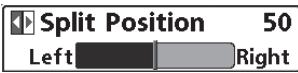
Split Position
Left Right Split Position allows you to adjust what percentage of the screen is taken up by the left side of any Combo View; each view may be adjusted independently; you must be in a specific view to adjust the screen size for that view. The number setting indicates the percentage taken up by the left side of the Combo View; selecting Left sets the left side of the screen to its smallest setting. The Split Position menu choice is only available when a Combo View is active.
To Adjust Split Screen Position:
- Highlight Split Position on the Side Imaging X-Press™ Menu.
- Use the RIGHT 4-WAY Cursor Control key to change the size of the left side of a split screen. (Left,30,40,50,60,70,Right,Default varies)
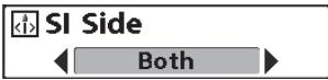
SI Side
SI Side sets which transducer beam from
the SI beams will be shown on the display.
To Adjust SI Side:
- Highlight SI Side on the Side Imaging X-Press™ Menu.
- Use the RIGHT 4-WAY Cursor Control key to select the transducer beam (Left, Both, Right, Default = Both)
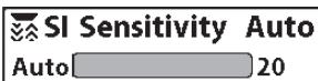
SI Sensitivity
SI Sensitivity controls how much detail is
shown on the display. Increasing the sensitivity shows more sonar returns from small baitfish and suspended debris in the water; however, the display may become too cluttered. When operating in very clear water or greater depths, increased sensitivity shows weaker returns that may be of interest. Decreasing the sensitivity eliminates the clutter from the display that is sometimes present in murky or muddy water. If SI Sensitivity is adjusted too low, the display may not show many sonar returns that could be fish.
To adjust the SI Sensitivity:
- Highlight SI Sensitivity on the Side Imaging X-Press™ menu.
- Use the LEFT or RIGHT 4-WAY Cursor Control keys to increase or decrease the SI Sensitivity setting. (Auto, 1 to 20, where Low = 1, High = 20, Default = 10)
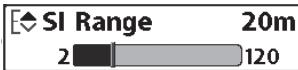
SI Range
SI Range sets the deepest range that will views. The range must be set manually. They be accessed from the Side Imaging Views.
To adjust the SI Range:
- From any Side Imaging View, highlight SI Range on the Side Imaging X-Press™ Menu.
- Use the LEFT or RIGHT 4-WAY Cursor Control keys to increase or decrease the SI Range setting. (6 to 360 feet or 2 to 120 meters [International Models only], Default = 150 feet or 50 meters)

Chart Speed
Chart Speed determines the speed at which
the side sonar information moves down the display, and consequently the amount of detail shown. A faster speed shows more information in the Side Imaging Views and is preferred by most anglers; however, the sonar information moves across the display quickly. A slower speed keeps the information on the display longer, allowing you to see an entire area. Adjust Chart Speed to your personal preference.
To adjust the Chart Speed:
- Highlight Chart Speed on the Side Imaging X-Press™ Menu.
- Use the LEFT or RIGHT 4-WAY Cursor Control keys to increase or decrease the Chart Speed setting. (1-9, Ultra, where 1 = Slow , 9 = Fast , Ultra = Fastest, Default = 5)
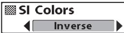
SI Colors
SI Colors allows you to select which color
palette you would like to use for the display.
To change the SI Colors:
- Highlight SI Colors on the Side Imaging X-Press™ menu.
- Use the LEFT or RIGHT 4-WAY Cursor Control keys to change the color palette. (Inverse, Gray, Brown, Blue, Green, Default = Blue)
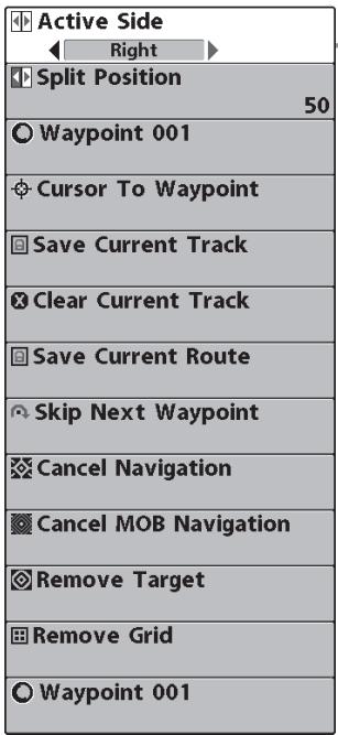
Navigation X-PressTM Menu
Navigation X-Press™ Menu
The Navigation X-Press™ Menu provides access to the settings most frequently used. Press the MENU key once while in the Bird's Eye View, the Chart or the Chart/Sonar Combo, Chart/Chart Combo View, or Chart/Bird's Eye Combo View to access the Navigation X-Press™ Menu.
NOTE: Menu choices will vary depending on system settings, such as whether you are currently navigating.
NOTE: You will have to change Active Side setting to Right to see the Navigation X-Press™ Menu from a Combo View with a sonar side.
Active Side allows you to select which side
of a Combo View will be active; key presses will only affect the active side of the screen. When a menu is displayed, the non-active side of the screen will be grayed out; at any other time, a green arrow will point to the active side. Combo Views usually display sonar on the left, with charts or Bird's Eye usually on the right. The Active Side menu choice is only available when a Combo View is active.
To select the Active Side:
- Highlight Active Side on the Navigation X-Press™ Menu.
- Use the RIGHT 4-WAY Cursor Control key to change which side is active. (Left, Right, Default = Left).

Split Position
50

Right
0
percentage of the screen is taken up by the left side of any Combo View, each view may be adjusted independently; you must be in a specific view to adjust the screen size for that view. The number setting indicates the percentage taken up by the left side of the Combo View; selecting Left sets the left side of the screen to its smallest setting. The Split Position menu choice is only available when a Combo View is active.
To Adjust Split Screen Position
- Highlight Split Position on the Navigation X-Press™ Menu.
- Use the RIGHT 4-WAY Cursor Control key to change the size of the left side of a split screen. (Left, 30, 40, 50, 60, 70, Right, Default varies)
Waypoint [Name] allows you to view the Waypoints submenu for the waypoint under your cursor.
To view the Waypoint [Name] Submenu:
- Move the cursor onto an existing waypoint and press the MENU key once, or use Cursor to Waypoint to select a waypoint from a list of saved waypoints.
- Highlight Waypoint [Name] on the Navigation X-Press™ menu.
- Use the RIGHT 4-Way Cursor Control key to view the Waypoints submenu, which contains the following menu choices:
![HUMMINBIRD 997C SI COMBO - To view the Waypoint [Name] Submenu: - 1](/content/2025/01/149493/images/66a8bf0217416b13b61d4894d558bbb81b203c8a61d437b75c2dbec7a9695a55.jpg)
Waypoint Submenu
The Waypoint Submenu contains the following menu choices:
Edit allows you to edit the Name, Position (Latitude and Longitude) and select the Icon that will be used to represent the waypoint in the Chart and Combo Views.
Delete allows you to delete a waypoint from the list of saved waypoints.
Target allows you to apply a target to a waypoint selected from the list of waypoints.
Grid allows you to apply a trolling grid to a waypoint selected from the list of waypoints.
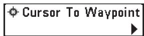
Cursor to Waypoint (Chart or Combo view only)
Cursor to Waypoint allows you to quickly move the cursor to any saved waypoint, so that you can locate it or edit it.
NOTE: This X-Press™ menu item appears only if you have saved waypoints.
To move cursor to a saved waypoint:
- Highlight Cursor to Waypoint on the Navigation X-Press™ menu.
- Use the RIGHT 4-WAY Cursor Control key to initiate Cursor to Waypoint.
- Use the UP or DOWN 4-WAY Cursor Control key to highlight the waypoint you wish to move the cursor to, then use the RIGHT 4-WAY Cursor Control key to select the destination waypoint.

Save Current Track
Save Current Track allows you to save the
current track being displayed. After the current track is saved, a new current track is started.
To Save Current Track:
- Highlight Save Current Track on the Navigation X-Press™ Menu.
- Use the RIGHT 4-WAY Cursor Control key to initiate saving the current track.
- The Confirm dialog box will appear. To save the current track, press the RIGHT Cursor key once more. To cancel saving the current track, press the LEFT Cursor key.

Clear Current Track
Clear Current Track allows you to clear the
current track being displayed and start a new track at the present position.
To Clear Current Track:
- Highlight Clear Current Track on the Navigation X-Press™ Menu.
- Use the RIGHT 4-WAY Cursor Control key to initiate clearing the current track.
- The Confirm dialog box will appear. To clear the current track, press the RIGHT Cursor key once more. To cancel clearing the current track, press the LEFT Cursor key.
Save Current Route allows you to save the current route being displayed. This menu choice will only appear when you are currently navigating a route.
To Save Current Route:
- Highlight Save Current Route on the Navigation X-Press™ Menu.
- Use the RIGHT 4-WAY Cursor Control key to initiate saving the current route.
- The Confirm dialog box will appear. To save the current route, press the RIGHT Cursor key once more. To cancel saving the current route, press the LEFT Cursor key.
Skip Next Waypoint
Skip Next Waypoint
(Only when navigating)
Skip Next Waypoint removes the next waypoint from the current route. This menu choice will only appear when you are currently navigating a route.
To Skip Next Waypoint:
- Highlight Skip Next Waypoint on the Navigation X-Press™ Menu.
- Use the RIGHT 4-WAY Cursor Control key to initiate skipping the next waypoint.
- The Confirm dialog box will appear. To skip the next waypoint, press the RIGHT Cursor key once more. To cancel skipping the next waypoint, press the LEFT Cursor key.
Cancel Navigation
Cancel Navigation
(Only when navigating)
Cancel Navigation discards the current route and exits Navigation Mode. This menu choice will only appear when you are currently navigating a route. This will not delete a previously-saved route.
To Cancel Navigation:
- Highlight Cancel Navigation on the Navigation X-Press™ Menu.
- Use the RIGHT 4-WAY Cursor Control key to initiate canceling navigation.
- The Confirm dialog box will appear. To cancel navigation, press the RIGHT Cursor key once more. To avoid canceling navigation, press the LEFT Cursor key.
Cancel MOB Navigation
Cancel MOB Navigation
(only when MOB Navigation is activated)
Cancel MOB Navigation removes the Man Overboard (MOB) waypoint and exits Man Overboard mode. This menu choice will only appear when you are currently navigating in Man Overboard mode.
To Cancel MOB Navigation:
- Highlight Cancel MOB Navigation on the Navigation X-Press™ menu.
- Use the RIGHT 4-WAY Cursor Control key to initiate canceling MOB navigation.
- The Confirm dialog box will appear. To cancel MOB navigation, press the RIGHT Cursor key once more. To avoid canceling MOB navigation, press the LEFT Cursor key.
Remove Target removes the waypoint target from the display. This menu choice will only appear when a target has already been applied to a waypoint.
To Remove a Target:
- Highlight Remove Target on the Navigation X-Press™ Menu.
- Use the RIGHT 4-WAY Cursor Control key to remove the target.
Remove Grid
Remove Grid
(Only if a Grid is active)
Remove Grid removes the waypoint grid from the display. This menu choice will only appear when a grid has already been applied to a waypoint.
To Remove a Grid:
- Highlight Remove Grid on the Navigation X-Press™ Menu.
- Use the RIGHT 4-WAY Cursor Control key to remove the grid.
Waypoint 8815
Waypoint [Name]
(Most recently-created waypoint)
Waypoint [Name] allows you to view the waypoints submenu for the most recently created waypoint.
NOTE: You must have pressed the MARK key at least once since you last powered up the Fishing System for this menu choice to appear.
To view the Waypoint [Name] Submenu:
- Move the cursor to the desired position and press the MARK key once to save a waypoint.
- Highlight Waypoint[Name] on the Navigation X-PressTM menu.
- Use the RIGHT 4-Way Cursor Control key to view the Waypoints submenu.
![HUMMINBIRD 997C SI COMBO - To view the Waypoint [Name] Submenu: - 1](/content/2025/01/149493/images/38211c36ec60a3f5514da496a35bf55ba06d954d0b07e0f963733e3bab33e456.jpg)
Waypoint [Name] Submenu
The Waypoint Submenu contains the following menu choices:
Edit allows you to edit the Name, Position (Latitude and Longitude) and select the Icon that will be used to represent the waypoint in the Chart and Combo Views.
Delete allows you to delete a waypoint from the list of saved waypoints.
Go To allows you to select a waypoint and start navigation toward that waypoint, or add that waypoint to the end of the current route.
Target allows you to apply a target to a waypoint selected from the list of waypoints.
Grid allows you to apply a trolling grid to a waypoint selected from the list of waypoints.
Snapshot and Recording X-PressTM Menu
| ○Start Recording |
| □Stop Recording |
| ○Delete Image |
| ○Delete All Images |
| ○Delete Recording |
| ○Delete All Recordings |
| ×Pings Per Second Auto |
| ▷Playback Speed |
| ▷Stop Playback |
Snapshot and Recording X-PressTM Menu
(Snapshot and Recording View only)
The Snapshot and Recording X-PressTM menu provides access to the image management and sonar recording functions. Press the MENU key once while in the Snapshot and Recording View to access the Snapshot and Recording X-PressTM menu.
NOTE: For more information, see Snapshot and Recording View.
Start Recording
Start Recording
(optional-purchase MMC/SD Card, Snapshot and
Recording View only)
Start Recording allows you to start sonar recording from the Snapshot and Recording View. This menu option is only available when you have an optional-purchase MMC/SD card installed and you are in Snapshot and Recording View.
To start sonar recording:
- Highlight Start Recording on the Snapshot and Recording X-Press™ menu, and press the RIGHT 4-Way Cursor key to start recording.
Stop Recording
Stop Recording
(optional-purchase MMC/SD Card only)
Stop Recording allows you to stop sonar recording. This menu option is only available when you have an optional-purchase MMC/SD card installed.
To stop sonar recording:
- To stop recording, highlight Stop Recording from any X-Press™ menu.
- Press the RIGHT 4-Way Cursor key.

Delete Image
Delete Image
(optional-purchase MMC/SD Card, Snapshot and Recording View only)
Delete Image allows you to delete a single screen capture image from the Snapshot and Recording View. This menu option is only available when you have an optional-purchase MMC/SD card installed and you are in Snapshot and Recording View and you have selected an image thumbnail.
To delete an image:
- On the Screen Snapshot View, use the UP and DOWN 4-Way Cursor keys to select the image you want to delete.
- Highlight Delete Image on the Snapshot and Recording X-Press™ menu.
- Press the RIGHT 4-Way Cursor key to initiate this procedure.
- A Confirm Dialog box will appear. Select Yes to delete the image or No to cancel the operation.
Delete All Images allows you to delete all the images at once from the Snapshot and Recording View. This menu option is only available when you have an optional-purchase MMC/SD card installed and you are in Snapshot and Recording View.
To delete all images:
- From the Snapshot and Recording View, highlight Delete All Images on the Snapshot and Recording X-Press™ Menu.
- A confirmation dialog box will ask if you want to delete all images. Select Yes to delete, or No to change your mind.
Delete Recording allows you to delete a single sonar recording from the Snapshot and Recording View. This menu option is only available when you have an optional-purchase MMC/SD card installed, you are in Snapshot and Recording View.
To delete a recording:
- On the Snapshot and Recording View, use the UP and DOWN 4-Way Cursor keys to highlight the recording you want to delete.
- Highlight Delete Recording on the Snapshot and Recording X-Press™ menu.
- Press the RIGHT 4-Way Cursor key to initiate this procedure.
- A Confirm Dialog box will appear. Select Yes to delete the recording or No to cancel the operation.
Delete All Recordings allows you to delete all the recordings at once from the Snapshot and Recording View. This menu option is only available when you have an optional-purchase MMC/SD card installed and you are in Snapshot and Recording view.
To delete all recordings:
- From the Snapshot and Recording View, highlight Delete All Recordings on the Snapshot and Recording X-Press™ Menu.
- A confirmation dialog box will ask if you want to delete all recordings. Select Yes to delete, or No to change your mind.

Pings Per Second
(optional-purchase MMC/SD Card,
Snapshot and Recording View only)
Pings Per Second allows you to specify the maximum ping rate for the sonar recording currently in progress from the Snapshot and Recording View. This menu option is only available when you have an optional-purchase MMC/SD card installed and you are in Snapshot and Recording View and are actively recording (not playing back).
To specify the pings per second:
- Highlight Pings Per Second on the Snapshot and Recording X-Press™ menu, and press the RIGHT 4-Way Cursor key to increase and decrease the number in the menu bar. (1-AUTO, Default = AUTO)

Playback Speed
(optional-purchase MMC/SD Card,
Snapshot and Recording View only)
Playback Speed allows you to specify the playback speed for a sonar recording from the Snapshot and Recording View. This menu option is only available when you have an optional-purchase MMC/SD card installed and you are playing back a recording.
To specify playback speed:
- Highlight Playback Speed on the Snapshot and Recording X-Press™ menu, and press the LEFT or RIGHT 4-Way Cursor key to display the following Playback Speed submenu choices (which are represented by icons): Beginning, Rewind2, Rewind, Reverse Normal, Reverse Slow, Pause, Slow Play, Normal Play, FF, FF2, End.
NOTE: You can also change playback speed in the Snapshot and Recording View using the Left and Right 4-Way Cursor keys, although you cannot skip to the beginning or end of a recording using these keys.
NOTE: Sonar chart speed is increased during Fast Forward and reversed during Rewind. This may result in a reduced quality sonar image, since at higher speeds, not every sonar return can be processed.
StopPlayback
StopPlayback
(optional-purchase MMC/SD Card only)
Stop Playback allows you to stop playback of a sonar recording from any view. This menu option is only available when you have an optional-purchase MMC/SD card installed and you are playing back a recording.
To stop playback of a recording:
- Highlight Stop Playback on any X-Press™ menu.
- Press the RIGHT 4-Way Cursor key to initiate this procedure.
To start playback, use the 4-Way Cursor keys to highlight a recording icon, then press the RIGHT 4-Way Cursor key to start playback (represented by a green "play" triangle which appears to the right of the recording icon).
NOTE: During playback, the amount of time/memory left to play is indicated by the status bar. For more information, see Snapshot and Recording View.
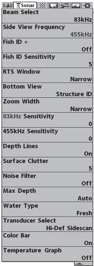
Sonar Menu
Sonar Menu Tab
Press the MENU key twice to access the Main Menu System and then press the RIGHT Cursor key to select the Sonar tab.
NOTE: Menu choices will vary depending on system settings such as whether the unit is set for Advanced User mode or what transducer is currently selected.
the transducer will be displayed on the screen.
When set to 200 / 83kHz , the returns from both beams are blended. The Split Sonar View continues to display the sonar returns from each beam in their respective windows. The blended information is shown in the Sonar View. The RTS® Window in the Sonar View will only show the returns from the 200kHz narrow beam.
When set to 200kHz , only the returns from the 200kHz narrow beam will be displayed in the Sonar View. The Split Sonar View will continue to display returns from both beams in their respective windows. The RTS^® Window in the Sonar View will display the returns from the 200kHz narrow beam.
When set to 83kHz , the returns from the 83kHz wide beam will be displayed in the Sonar View. The Split Sonar View will continue to display returns from both beams in their respective windows. The RTS^® Window will display the returns from the 83kHz wide beam.
To use Beam Select:
- Highlight Beam Select on the Sonar main menu.
- Use the LEFT or RIGHT 4-WAY Cursor Control keys to select either the 200kHz beam, the 83kHz beam or the 200/83kHz beam. (200/83 kHz, 200 kHz, 83 kHz, Default = 200 kHz)
Side View Frequency allows you to select which frequency to apply to the side-looking beams (800 kHz or 455 kHz).
To change the Side View Frequency:
- Highlight Side View Frequency on the Sonar main menu.
- Use the LEFT or RIGHT 4-WAY Cursor Control keys to select either the 800kHz beam or the 455kHz beam. (800 kHz or 455 kHz; Default = 455 kHz)
Fish ID + ^TM uses advanced signal processing
to interpret sonar returns, and will display a Fish Symbol when very selective requirements are met. When a fish is detected, a fish icon and its depth are displayed above the return that has been classified as being a fish. Three different fish size icons represent the intensity of the sonar return, and provide an indicator of relative fish size.
DualBeam PLUS™ sonar models represent targets detected in the 200 kHz narrow beam as orange fish symbols, and represent targets detected in the 83 kHz wide beam as blue fish symbols.
200 kHz, narrow beam orange fish symbols
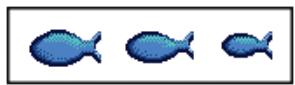
83 kHz, wide beam blue fish symbols
When Fish ID + ^TM is turned off, the 900 Series ^TM shows only the raw sonar returns on the display. These returns will often result in "arches" forming on the display, indicating potential targets. Due to the transducer beam angle, the distance to a fish decreases as the fish moves into the beam, and then increases as it moves out again, creating a Fish Arch when this distance change is shown on the display. Boat speed, chart speed, and the position of the fish within the sonar beam greatly affect the shape of the arch.
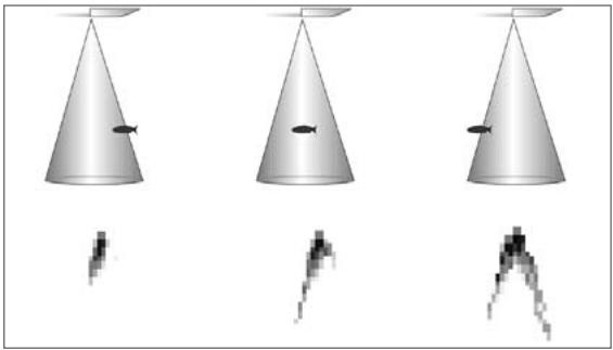
Transducer Cone and Fish Arches
To turn Fish ID + ^TM on or off:
- Highlight Fish ID+ on the Sonar main menu.
- Use the LEFT or RIGHT 4-WAY Cursor Control keys to turn the Fish ID+TM setting On or Off. (Off, On, Default = Off)
the Fish ID^+^TM detection algorithms. Selecting a higher setting allows weaker returns to be displayed as fish. This is useful for identifying smaller fish species or baitfish. Selecting a lower setting displays fewer fish from weak sonar returns. This is helpful when seeking larger species of fish. Fish Sensitivity is used in conjunction with Fish ID^+^TM . Fish ID^+^TM must be On for Fish Sensitivity to affect the ability of the 900 Series™ to identify sonar returns as fish.
To change the Fish ID Sensitivity setting:
- Highlight Fish ID Sensitivity on the Sonar main menu.
- Use the LEFT or RIGHT 4-WAY Cursor Control keys to change the Fish Sensitivity setting. (Low = 1, High = 10, Default = 5)
either Wide or Narrow, or turns it off in the Sonar View. The RTS® Window always updates at the fastest rate possible and only displays returns that are within the transducer beam. (See Getting Started - Using Your 900 Series™: Real Time Sonar [RTS®] Window for more information.)
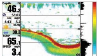
RTS® Window (Wide)
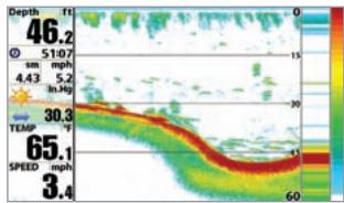
RTS Window (Narrow)
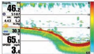
RTS® Window (Off)
To change the RTS® Window setting:
- Highlight RTS® Window on the Sonar main menu.
- Use the LEFT or RIGHT 4-WAY Cursor Control keys to change the RTS® Window setting. (Wide, Narrow, Off, Default = Narrow)
Bottom View

Bottom View
Bottom View selects the method used to
represent bottom and structure on the display. Structure ID® represents weak returns in blue and strong returns in red. WhiteLine® highlights the strongest sonar returns in white resulting in a distinctive outline. This has the benefit of clearly defining the bottom on the display. See Bottom Presentation for more information.
To adjust the Bottom View:
- Highlight Bottom View on the Sonar Main Menu.
- Use the LEFT or RIGHT 4-WAY Cursor Control keys to change the Bottom View setting. (Structure ID, WhiteLine, Default = Structure ID)
Zoom Width
(Sonar Zoom View only)
Zoom Width allows you to control the width of the Zoomed Sonar (the left-hand side of the screen).
To change the Zoom Width:
- Highlight Zoom Width on the Sonar Main menu.
- Use the LEFT or RIGHT 4-WAY Cursor Control keys to change the width of the Zoomed Sonar. (Narrow, Medium, Wide, Default = Narrow)
83 kHz Sensitivity (Advanced)
83 kHz Sensitivity changes the sensitivity of the 83 kHz beam. Increasing the 83 kHz Sensitivity will display additional weak returns and decreasing the 83 kHz Sensitivity will display fewer weak returns. The 83 kHz Sensitivity menu choice is only available when User Mode is set to Advanced (see Setup Menu Tab: User Mode).
To set the 83 kHz Sensitivity:
- Make sure you are in Advanced User Mode, then highlight 83 kHz Sensitivity on the Sonar main menu.
- Use the LEFT or RIGHT 4-WAY Cursor Control keys to set the 83kHz Sensitivity. (-10 to +10, Default = 0)
455 kHz Sensitivity
(Advanced, with optional purchase QuadraBeam PLUS™ transducer)
455 kHz Sensitivity adjusts the sensitivity of the 455 kHz beam. Increasing the sensitivity will display additional weak returns and decreasing the sensitivity will display fewer weak returns. A QuadraBeam PLUS™ transducer must be attached to the Fishing System. The 455 kHz Sensitivity menu choice is available when Transducer Select is set to QuadraBeam (see Sonar Menu Tab: Transducer Select) and User Mode is set to Advanced (see Setup Menu Tab: User Mode).
NOTE: The 455 kHz Sensitivity requires the purchase of the QuadraBeam PLUS™ transducer.
You can visit our website at www.humminbird.com to order this accessory online or contact our Customer Resource Center at 1-800-633-1468.
NOTE: 455 kHz Sensitivity is particularly useful for adjusting the sensitivity of the 455 kHz sonar returns in the Side Beam View. The 455 kHz sensitivity can be adjusted without affecting the sensitivity of the 200 kHz returns shown in the 200 kHz sonar window.
To change the 455kHz Sensitivity setting:
- Make sure you have selected QuadraBeam Transducer and Advanced Mode and that the QuadraBeam PLUS™ transducer is connected, then highlight 455 kHz Sensitivity on the Sonar Main Menu.
- Use the LEFT or RIGHT 4-WAY Cursor Control keys to change the 455kHz Sensitivity. (-10 to +10, Default = 0)
Depth Lines

Depth Lines
(Advanced)
Depth Lines divide the display into four equal sections that are separated by three horizontal depth lines. The depth of each line is displayed along the depth scale. You can either turn Depth Lines On or Off. The Depth Lines menu choice is available when User Mode is set to Advanced (see Setup Menu Tab: User Mode).
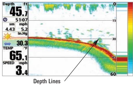
To change the Depth Lines setting:
- Make sure you are in Advanced User Mode, then highlight Depth Lines on the Sonar main menu.
- Use the LEFT or RIGHT 4-WAY Cursor Control keys to turn the Depth Lines setting On or Off. (Off, On, Default = On)
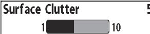
Surface Clutter
(Advanced)
Surface Clutter adjusts the filter that removes surface clutter noise caused by algae and aeration. The lower the setting, the less surface clutter will be displayed. The Surface Clutter menu choice is available when User Mode is set to Advanced (see Setup Menu Tab: User Mode).
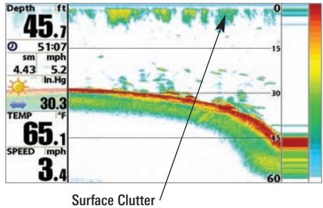
To change the Surface Clutter setting:
- Make sure you are in Advanced User Mode, then highlight Surface Clutter on the Sonar main menu.
- Use the LEFT or RIGHT 4-WAY Cursor Control keys to change the Surface Clutter setting. (Low = 1 to High = 10, Default = 5)
Noise Filter

Noise Filter
(Advanced)
Noise Filter adjusts the sonar Noise Filter to limit interference on the display from sources such as your boat engine, turbulence, or other sonar devices. The Noise Filter menu choice is available when User Mode is set to Advanced (see Setup Menu Tab: User Mode).
NOTE: The Off setting removes all filtering; Low, Medium and High settings add progressive filtering of the sonar returns. In some deep water situations, the High setting may actually make it harder for the control head to find the bottom.
To change the Noise Filter setting:
- Make sure you are in Advanced User Mode, then highlight Noise Filter on the Sonar main menu.
- Use the LEFT or RIGHT 4-WAY Cursor Control keys to change the Noise Filter setting. (Off, Low, Medium, High 1, High 2, High 3, Default = Low)
Max Depth adjusts the maximum depth of operation. The performance of your 900 Series™ can be tuned to the maximum depth you will be fishing in by setting the Max Depth. When a maximum depth is set, your 900 Series™ will not attempt to acquire sonar data below that depth, thus increasing overall performance. When Max Depth is set to Auto, the 900 Series™ will acquire bottom readings as needed (within the capacity of the unit). If the bottom is deeper than the Max Depth setting, the digital depth readout will flash, indicating that the 900 Series™ cannot locate the bottom. The Max Depth menu choice is available when User Mode is set to Advanced (see Setup Menu Tab: User Mode).
To change the Max Depth setting:
- Make sure you are in Advanced User Mode, then highlight Max Depth on the Sonar main menu.
- Use the LEFT or RIGHT 4-WAY Cursor Control keys to change the Max Depth setting. (AUTO, 10 to 1500 feet; 3 to 500 meters [International models only], Default = AUTO)
Water Type configures your unit for operation in fresh or salt water. The Water Type menu choice is available when User Mode is set to Advanced (see Setup Menu Tab: User Mode).
NOTE: In salt water, what would be considered a large fish might be 2 to 10 times bigger than a large fish in fresh water (depending on the type of fish you are seeking). The salt water setting allows for a greater range in fish size adjustment to account for this. Also, make sure that the Water Type is set accurately, especially in salt water, as this affects the accuracy of deep water depth readings.
To change the Water Type setting:
- Make sure you are in Advanced User Mode, then highlight Water Type on the Sonar main menu.
- Use the LEFT or RIGHT 4-WAY Cursor Control keys to change the Water Type setting. (Fresh, Salt, Default = Fresh)
Transducer Select Dual 50/200
Transducer Select
Transducer Select allows you to select which
transducer you want to use, High-Definition Sidescan, Compact Sidescan, Sidescan, QuadraBeam PLUS™, DualBeam PLUS™, Dual 50/200 kHz, or Universal Sonar 2.
NOTE: The transducer setting must correspond to the transducer type connected to your system.
NOTE: All transducer choices besides the High Definition Sidescan transducer require a separate purchase..
To change the selected Transducer:
- Highlight Transducer Select on the Sonar Main menu.
- Use the LEFT or RIGHT 4-WAY Cursor Control keys to change the transducer selected. (Hi-Def Sidescan, Compact Sidescan, Sidescan, Quad Beam, Dual Beam, Dual 50/200, Universal Sonar 2, Default = Hi-Def Sidescan)

Color Bar
Color Bar allows you to display or suppress
the display of the color bar shown in the full screen Sonar View.
To change the display of the Color Bar:
- Highlight Color Bar on the Sonar Main menu.
- Use the LEFT or RIGHT 4-WAY Cursor Control keys to change the display of the color bar. (Off, On, Default = On)
Temperature Graph

Temperature Graph
(Sonar View only, with Temperature input)
Temperature Graph allows you to display or suppress a water temperature graph over the main Sonar View to show temperature changes correlated to recent sonar history.
To change the display of the Temperature Graph:
- In the Sonar View, highlight Temperature Graph on the Sonar main menu.
- Use the LEFT or RIGHT 4-WAY Cursor Control keys to change the display of water temperature. (Off, On, Default = On)
Navigation Menu
| Current Track | |
| Saved Tracks | |
| Waypoints | |
| Routes | |
| Chart Orientation North-Up | |
| North Reference True | |
| Trolling Grid Rotation 0° | |
| Trackpoint Interval 1 second | |
| Track Min Distance 5m | |
| Track Color Range 20m | |
| Map Datum WGS 84 (Default) | |
| Course Projection Line Visible | |
| Export All Nav Data | |
| Delete All Nav Data | |
| Continuous Navigation Mode Off |
Navigation Menu Tab
Press the MENU key twice to access the Main Menu System, then press the RIGHT cursor key to select the Navigation tab.
NOTE: Menu choices will vary depending on system settings.
Current Track
Current Track
Current Track allows you to view the Current Track submenu.
To view the Current Track Submenu:
- Highlight Current Track on the Navigation main menu.
- Use the RIGHT 4-WAY Cursor Control keys to view the Current Track submenu.
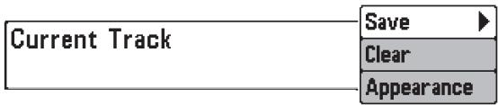
Current Track Submenu
The Current Track Submenu contains the following menu choices:
Save Current Track allows you to save the current track.
Clear Current Track allows you to clear the current track.
Appearance allows you to change the style and color of the current track. (Breadcrumb Trail, Dashed Line, Solid Line or Wide Line, and if a line, the color of the line, or Color By Depth. If you choose Color By Depth, you cannot choose one color to represent the track; a color range will represent the different depths on the track instead, from light green (shallowest) to black (deepest). You can change the depth range associated with black by using Track Color Range menu setting (see Navigation Main Menu: Track Color Range).
Saved Tracks allows you to view the Saved Tracks submenu.
To view the Saved Tracks Submenu:
- Highlight Saved Tracks on the Navigation main menu.
- Use the RIGHT 4-WAY Cursor Control keys to view the Saved Tracks submenu.
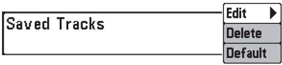
Saved Tracks Submenu
The Saved Tracks Submenu contains the following menu choices:
Edit allows you to select a previously-saved track and edit its name, whether it is visible or not, and its appearance.
Delete allows you to delete a track from a list of previously-saved tracks.
Default sets the appearance of the track created by selecting Save Current Track.
Waypoints
Waypoints
Waypoints allows you to view the Waypoints submenu.
To view the Waypoints Submenu:
- Highlight Waypoints on the Navigation main menu.
- Use the RIGHT 4-WAY Cursor Control keys to view the Waypoints submenu.
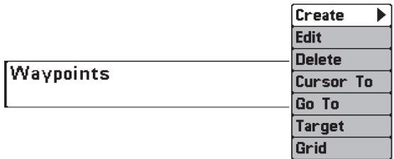
Waypoints Submenu
The Waypoints Submenu contains the following menu choices:
Create allows you to create a new waypoint and edit it immediately. The current boat position will be used as the default, but you can set the coordinates to any valid position. The Icon used to represent the waypoint in the Chart and Combo Views can also be changed.
Edit allows you to choose from a list of previously-saved waypoints, then edit the Name, Position (Latitude and Longitude) and select the Icon that will be used to represent the waypoint in the Chart and Combo Views.
Delete allows you to delete a waypoint from the list of saved waypoints.
Cursor To allows you to move the cursor quickly to a waypoint selected from the list of saved waypoints.
Go To allows you to select a waypoint and start navigation toward that waypoint, or add that waypoint to the end of the current route.
Target allows you to apply a target to a waypoint selected from the list of waypoints.
Grid allows you to apply a trolling grid to a waypoint selected from the list of waypoints.
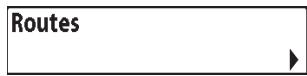
Routes
Routes allows you to view the Routes menu.
To view the Routes Submenu:
- Highlight Routes on the Navigation main menu.
- Use the RIGHT 4-WAY Cursor Control keys to view the Routes submenu.
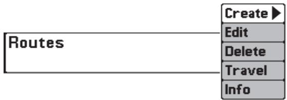
Routes Submenu
The Routes Submenu contains the following menu choices:
Create allows you to create a new, empty route and add waypoints to it immediately.
Edit allows you to select a previously-saved route and edit its name and the waypoints on it.
Delete allows you to delete a route from a list of previously-saved routes.
Travel allows you to select a previously-saved route to use as the current route; this menu setting also begins navigation on this route. Routes can be traveled in either the forward or reverse direction.
Info displays information about the route, including the distance and bearing from each waypoint to the next.
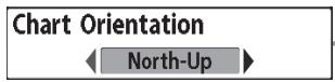
Chart Orientation
Chart Orientation allows you to select
whether the views containing charts should be drawn North-Up or Course-Up.
To change the Chart Orientation setting:
- Highlight Chart Orientation on the Navigation main menu.
- Use the LEFT or RIGHT 4-WAY Cursor Control keys to change the Chart Orientation setting. (North-Up, Course-Up, Default = North-Up)
NOTE: The Chart Orientation setting does not apply to the Bird's Eye View.

North Reference
North Reference allows you to have bearings
displayed with one of two orientations: True North or Magnetic North.
To change the North Reference setting:
- Highlight North Reference on the Navigation main menu.
- Use the LEFT or RIGHT 4-WAY Cursor Control keys to change the North Reference setting. (True, Magnetic, Default = True)
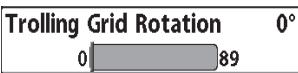
Trolling Grid Rotation
Trolling Grid Rotation allows you to set the
orientation of the trolling grid in degrees, where a setting of 0^ displays a standard North, South, East, West alignment. See Waypoints for information on how to set a Grid.
To change the Trolling Grid Rotation setting:
- Highlight Trolling Grid Rotation on the Navigation main menu.
- Use the LEFT or RIGHT 4-WAY Cursor Control keys to change the Trolling Grid Rotation setting. (0^ to 89^ , Default = 0^ )
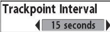
Trackpoint Interval
Trackpoint Interval allows you to select the
time period between trackpoints. The current track can only contain up to 20,000 trackpoints, so longer time periods cause the track to extend back further in time, but will be less detailed.
NOTE: Trackpoint Interval works in conjunction with Track Min Distance. Both conditions must be met before a trackpoint is added to the current track.
To change the Trackpoint Interval setting:
- Highlight Trackpoint Interval on the Navigation main menu.
- Use the LEFT or RIGHT 4-WAY Cursor Control keys to change the Trackpoint Interval setting. (1 second, 5 seconds, 10 seconds, 15 seconds, 30 seconds or 60 seconds, Default = 1 second)
NOTE: During slow travel or drift, setting both Trackpoint Interval and Track Min Distance to small values will allow you to increase the track resolution.
Track Min Distance 16ft

Track Min Distance
(Advanced)
Track Min Distance allows you to set a minimum distance of travel before a trackpoint is added to the track.
NOTE: Track Min Distance works in conjunction with Trackpoint Interval. Both conditions must be met before a trackpoint is added to the current track.
To change the Track Minimum Distance setting:
- Make sure you are in Advanced User Mode, then highlight Track Min Distance on the Navigation main menu.
- Use the LEFT or RIGHT 4-WAY Cursor Control keys to change the Track Min Distance setting. (1 to 300 feet or 1 to 100 meters [International Units only], Default = 16 ft, 5 m)
NOTE: During slow travel or drift, setting both Trackpoint Interval and Track Min Distance to small values will allow you to increase the track resolution.
Track Color Range

Track Color Range
Track Color Range allows you to set the depth
range that will be displayed as black, the deepest depth, when Color By Depth is selected as the style for the current track (see Navigation Menu Tab: Current Track).
NOTE: Only an optional-purchase transducer with a 50kHz frequency will allow you to track to 3000 feet.
To change the Track Color Range:
- Highlight Track Color Range on the Navigation main menu.
- Use the LEFT or RIGHT 4-WAY Cursor Control keys to change the Track Color Range setting. (50 to 3000 feet or 20 to 1000 meters [International Units only], Default = 50 ft, 20 m)
Map Datum
WGS84(Default)
Map Datum
(Advanced)
Map Datum allows you to change the map coordinate system used by the 900 Series™ to match those of a paper map.
To change the Map Datum setting:
- Make sure you are in Advanced User Mode, then highlight Map Datum on the Navigation main menu.
- Use the LEFT or RIGHT 4-WAY Cursor Control keys to change the Map Datum setting. (Default = WGS 84)
Course Projection Line
Course Projection Line allows you to display
or hide an arrow extending from the bow of the boat that projects your current course, and shows where the boat will go if you continue on your present course.
To change the Course Project Line setting:
- Highlight Course Projection Line on the Navigation main menu.
- Use the LEFT or RIGHT 4-WAY Cursor Control keys to change the Course Projection Line setting (Hidden, Visible, Default = Visible)
Export All Nav Data
Export All Nav Data
(Advanced)
Export All Nav Data allows you to export all saved Tracks, Waypoints and Routes to an MMC/SD card.
To Export All Navigation Data:
- Make sure you are in Advanced User Mode, and that an optional purchase MMC/SD card is installed in the slot, then highlight Export All Nav Data on the Navigation main menu.
- Use the RIGHT 4-WAY Cursor Control key to export all navigation data.
Delete All Nav Data
Delete All Nav Data
(Advanced)
Delete All Nav Data allows you to delete all saved Tracks, Waypoints and Routes. This menu choice should be used with caution.
To Delete All Navigation Data:
- Make sure you are in Advanced User Mode, then highlight Delete All Nav Data on the Navigation main menu.
- Use the RIGHT 4-WAY Cursor Control key to delete all navigation data.
Continuous Navigation Mode
Off
Continuous Navigation Mode
Continuous Navigation Mode allows you to
continue to navigate and fish around a particular waypoint, even if you pass over it multiple times.
To activate or de-activate Continuous Navigation:
- Highlight Continuous Navigation Mode on the Navigation main menu.
- Use the LEFT or RIGHT 4-WAY Cursor Control keys to turn Continuous Navigation Mode On or Off (Off, On, Default = Off)
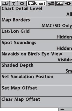
Chart Menu
Chart Menu Tab
Press the MENU key twice to access the Main Menu System and then press the RIGHT Cursor key to select the Chart tab.
NOTE: Menu choices will vary depending on system settings such as whether the unit is set for Advanced User mode.
Chart Detail Level

Chart Detail Level
Chart Detail Level allows you to select how
much chart detail you want displayed on the Navigation Views. Basic shows land areas, ports, obstructions and restricted areas. Navigation shows navaids, landmarks, ferryways and navigation routes in addition to the Basic information. Underwater shows depth contours, fishing areas, underwater wrecks, tides and currents in addition to the Basic and Navigation information. All shows roads, buildings, railways, and other notations in addition to the Basic, Navigation and Underwater information.
To change the Chart Detail Level setting:
- Highlight Chart Detail Level on the Navigation main menu.
- Use the LEFT or RIGHT 4-WAY Cursor Control keys to change the Chart Detail Level setting. (Basic, Navigation, Underwater, All, Default = All)
NOTE: Some chart details are only available with optional-purchase MMC/SD cards.
map borders. A Map Border indicates an area which contains a different map.
Map Borders, shown with Optional-Purchase Navionics Cartography
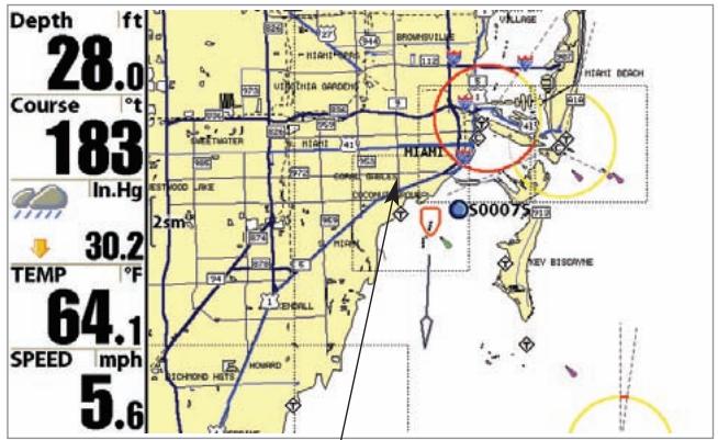
Map Borders
To change the Map Borders setting:
- Highlight Map Borders on the Navigation main menu.
- Use the LEFT or RIGHT 4-WAY Cursor Control keys to change the Map Borders setting. (Hidden, MMC/SD Only, All Visible, Default = MMC/SD Only)
Lat/Lon Grid allows you to display or hide a grid showing latitude and longitude lines.
To change the Lat/Lon Grid setting:
- Highlight Lat/Lon Grid on the Navigation main menu.
- Use the LEFT or RIGHT 4-WAY Cursor Control keys to change the Lat/Lon Grid setting. (Hidden, Visible, Default = Hidden)
Spot Soundings
Hidden
Spot Soundings
Spot Soundings allows you to display or
hide spot soundings, which are depth measurements shown on the chart.
NOTE: Spot Soundings are only available with optional-purchase MMC/SD cards.
To change the Spot Soundings setting:
- Highlight Spot Soundings on the Navigation main menu.
- Use the LEFT or RIGHT 4-WAY Cursor Control keys to change the Spot Soundings setting. (Hidden, Visible, Default = Hidden)
display or hide additional navigational aids, such as lights and buoys, in Bird's Eye View.
NOTE: You will see more navigational aids with and optional-purchase MMC/SD card.
To change the Navaids on Bird's Eye View setting:
- Highlight Navaids on Bird's Eye View on the Chart main menu.
- Use the LEFT or RIGHT 4-WAY Cursor Control keys to change the Navaids on Bird's Eye View setting. (Hidden, Visible, Default = Visible)
| Shaded Depth | 16ft |
| Off | 60 |
Shaded Depth
Shaded Depth allows you to change the
depth used for shading on the chart views.
To change the Shaded Depth setting:
- Highlight Shaded Depth on the Navigation main menu.
- Use the LEFT or RIGHT 4-WAY Cursor Control keys to change the Shaded Depth setting. (Off, 1 to 60 Feet or 1 to 20 Meters [International Units only], Default = 15 ft, 5 m)
Set Simulation Position allows you to set the position of the boat used in the Simulator.
To set the Simulation Position:
- Activate the cursor and move it to the coordinates from where you want simulation to start.
NOTE: The cursor must be active in order for this procedure to work.
- Make sure you are in Advanced User Mode, then highlight Set Simulation Position on the Navigation main menu.
- Use the RIGHT 4-WAY Cursor Control key to change the Simulation Position setting. A confirmation dialog box will appear to allow you to change your mind, or to confirm your choice. If the cursor was not active before you began this procedure, you will see an error message. Exit the menu, set the cursor, then try again.
Set Map Offset
Set Map Offset
(Advanced)
Set Map Offset allows you to change the map offset used by the 900 Series™.
NOTE: The Map Offset will be applied to all maps and not just the map that requires the correction. The Map Offset should be cleared if a different map is to be used.
To change the Map Offset setting:
- Activate the cursor and move it location where the Map Offset will be applied.
NOTE: The cursor must be active in order for this procedure to work.
- Make sure you are in Advanced User Mode, then highlight Set Map Offset on the Navigation main menu.
- Use the RIGHT 4-WAY Cursor Control key to set the Map Offset. A confirmation dialog box will appear to allow you to change your mind, or to confirm your choice. If the cursor was not active before you began this procedure, you will see an error message. Exit the menu, set the cursor, then try again.
Clear Map Offset
Clear Map Offset
(Advanced)
Clear Map Offset allows you to clear the Map Offset. Clear Map Offset is only accessible if a Map Offset is currently active.
To Clear Map Offset:
- Make sure you are in Advanced User Mode, then highlight Clear Map Offset on the Navigation main menu.
- Use the RIGHT 4-WAY Cursor Control key to clear the Map Offset.
Alarms Menu
| Depth Alarm | Off |
| Fish ID Alarm | |
| Low Battery Alarm | Off |
| Aux. Temp. Alarm | Off |
| Temp. Alarm | Off |
| Off Course Alarm | 328ft |
| Arrival Alarm | 164ft |
| Drift Alarm | Off |
| Alarm Tone | Medium |
Alarms Menu Tab
From any view, press the MENU key twice to access the Main Menu System. The Alarms tab will be the default selection.
NOTE: When an alarm is triggered, you can silence it by pressing any key. The alarm will be silenced, and will not be triggered again until a new instance of the alarm condition is detected.
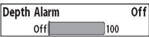
Depth Alarm
Depth Alarm sounds when the depth
becomes equal to or less than the menu setting.
To change the Depth Alarm setting:
- Highlight Depth Alarm on the Alarms main menu.
- Use the LEFT or RIGHT 4-WAY Cursor Control keys to change the Depth Alarm setting. (OFF, 1 to 100 feet, or 0.5 to 30 meters [International models only], Default = OFF)
Fish ID Alarm

Fish ID Alarm
Fish ID Alarm sounds when the
900 Series™ detects fish that correspond to the alarm setting. Fish ID Alarm will only sound if Fish ID + ^TM is on.
For example, if you've set the Fish ID Alarm to sound for Large fish only, the Fish ID alarm will sound when a large-sized fish is detected.
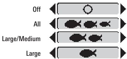
To change the Fish ID Alarm setting:
- Highlight Fish ID Alarm on the Alarms main menu.
- Use the LEFT or RIGHT 4-WAY Cursor Control keys to change the Fish ID Alarm setting. (Off, All, Large/Medium, Large, Default = Off)
| Low Battery Alarm | Off | |
| Off | 13.5 | |
Low Battery Alarm
Low Battery Alarm sounds when the input
battery voltage is equal to or less than the menu setting. The battery alarm will only sound for the battery that is connected to the 900 Series™. The Low Battery Alarm should be set to warn you when the battery voltage drops below the safety margin that you have determined. For instance, if you are running a trolling motor (battery operated), you would want to set the Low Battery Alarm to sound before the battery voltage drops too low for it to be used to start your main, gasoline-powered engine.
To change the Low Battery Alarm setting:
- Highlight Low Battery Alarm on the Alarms main menu.
- Use the LEFT or RIGHT 4-WAY Cursor Control keys to change the Low Battery Alarm setting. (Off, 8.5V - 13.5V, Default = Off)
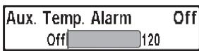
Aux Temp Alarm
(with optional-purchase temp. probe or Temp/Speed only)
Aux Temp Alarm sounds when the water temperature from the Paddlewheel/Temperature Probe detected by the Fishing System reaches the Aux Temp Alarm setting, which is either set in degrees Fahrenheit or Celsius [International Models only]. For example, if the Aux Temp Alarm is set to 58 degrees Fahrenheit, and the water temperature falls from 60 degrees to 58 degrees, the Aux Temp Alarm will sound. Similarly, if the water temperature rises from 56 degrees to 58 degrees, the Temp Alarm will also sound.
To change the Aux Temp Alarm setting:
- Highlight Aux Temp Alarm on the Alarms main menu.
- Use the LEFT or RIGHT 4-Way Cursor Control keys to change the Aux Temp Alarm setting. (Off, 33-120 [Fahrenheit], 0-50 [Celsius], Default = Off)
temperature detected by the 900 Series™ reaches the Temp Alarm setting, which is either set in degrees Fahrenheit or Celsius [International models only]. For example, if the Temp Alarm is set to 58^ Fahrenheit, and the water temperature falls from 60^ to 58^ , the Temp Alarm will sound. Similarly, if the water temperature rises from 56^ to 58^ , the Temp Alarm will also sound.
To change the Temp Alarm setting:
- Highlight Temp Alarm on the Alarms main menu.
- Use the LEFT or RIGHT 4-Way Cursor Control keys to change the Temp Alarm setting. (Off, 32-120 [Fahrenheit], 0-50 [Celsius (International models only)], Default = Off)
has moved too far off course based on the menu setting when navigating. Off Course Alarm allows you to set how far the boat is allowed to move off course before the Off Course Alarm will sound.
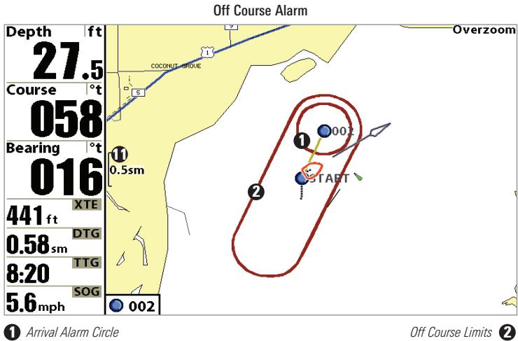
To change the Off Course Alarm setting:
- Highlight Off Course Alarm on the Alarms main menu.
- Use the LEFT or RIGHT 4-WAY Cursor Control keys to change the Off Course Alarm setting. (Off, 25 to 3000 feet, 10 to 1000 meters [International models only], Default = 300 ft, 100 m)
Arrival Alarm sounds when the boat has
either exceeded the distance to the destination waypoint, or has entered the Arrival Alarm Circle, based on the menu setting when navigating. Arrival Alarm allows you to set how close the boat must be to the destination waypoint before the Arrival Alarm will sound.
To change the Arrival Alarm setting:
- Highlight Arrival Alarm on the Alarms main menu.
- Use the LEFT or RIGHT 4-WAY Cursor Control keys to change the Arrival Alarm setting. (Off, 25 to 3000 feet, 10 to 1000 meters [International models only], Default = 150 ft, 50 m)
Drift Alarm sounds when the boat has
exceeded the distance from the boat's anchored position, based on the menu setting. Drift Alarm allows you to set the size of a perimeter around the boat's anchored position; if the anchored boat drifts outside of that perimeter, the Drift Alarm will sound.
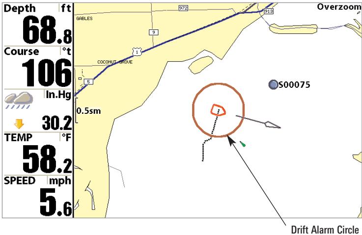
To change the Drift Alarm setting:
- Highlight Drift Alarm on the Alarms main menu.
- Use the LEFT or RIGHT 4-WAY Cursor Control keys to change the Drift Alarm setting. (Off, 25 to 3000 feet, 10 to 1000 meters [International models only], Default = Off)

Alarm Tone
Alarm Tone selects the pitch of the alarm
sound. A brief tone will be produced as you adjust the Alarm Tone so that you can select the tone that you can hear best.
To change the Alarm Tone setting:
- Highlight Alarm Tone on the Alarms main menu.
- Use the LEFT or RIGHT 4-WAY Cursor Control keys to change the Alarm Tone setting. (High, Medium, Low, Default = Medium)
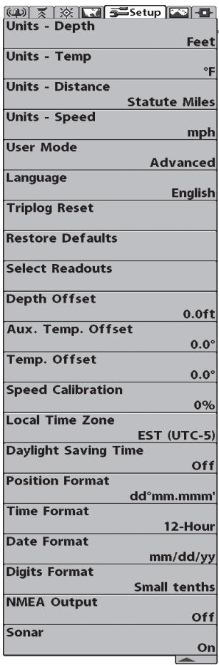
Setup Menu
Setup Menu Tab
From any view, press the MENU key twice to access the tabbed Main Menu System, then press the RIGHT cursor key until the Setup tab is selected.
NOTE: Menu choices will vary depending on system settings such as whether the unit is set for Advanced User mode and what accessories are attached to the control head.
To change the Units - Depth setting:
- Highlight Units - Depth on the Setup menu.
- Use the LEFT or RIGHT 4-WAY Cursor Control keys to change the Units - Depth setting. (Meters [International models only], Feet, Fathoms; Default is Meters for International models, and Feet for Domestic models)
Units - Temp

Units - Temp
(International only)
Units - Temp selects the units of measure for all temperature-related readouts. International models only.
To change the Units - Temp setting:
- Highlight Units - Temp on the Setup menu.
- Use the LEFT or RIGHT 4-WAY Cursor Control keys to change the Units - Temp setting. (Celsius, Fahrenheit; Default = Celsius)
Units - Distance
Feet/Statute Miles
Units - Distance
(with Speed input only)
Units - Distance selects the units of measure for all distance-related readouts.
To change the Units - Distance setting:
- Highlight Units - Distance on the Setup menu.
- Use the LEFT or RIGHT 4-WAY Cursor Control keys to change the Units - Distance setting. (Domestic Models: Statute Miles, Nautical Miles; Default = Statute Miles; International Models: Meters/Kilometers, Meters/Nautical Miles, Feet/Statute Miles, Feet/Nautical Miles; Default = Meters/Kilometers)
Units - Speed

Units - Speed
(with Speed input only)
Units - Speed selects the units of measure for speed-related readouts.
To change the Units - Speed setting:
- Highlight Units - Speed on the Setup menu.
- Use the LEFT or RIGHT 4-WAY Cursor Control keys to change the Units - Speed setting. (kph [International models only], mph, kts, Default = kph for International models and mph for Domestic models)
Normal or Advanced. When set to Normal, only the basic menu options are shown. When set to Advanced (default setting), additional menu choices are available.
To change the User Mode setting:
- Highlight User Mode on the Setup menu.
- Use the LEFT or RIGHT 4-WAY Cursor Control keys to change the User Mode setting. (Normal, Advanced, Default = Advanced)
Language
English
Language
(International only)
Language selects the display language for menus. International models only.
To change the Language setting:
- Highlight Language on the Setup menu.
- Use the LEFT or RIGHT 4-WAY Cursor Control keys to change the Language setting. (Default = English)
Triplog Reset
Triplog Reset
( with Speed input only)
Triplog Reset resets the Triplog to zero. The Triplog provides the following information: timer for elapsed time, distance traveled since last reset, and average speed.
To Reset Triplog:
- Highlight Reset Triplog on the Setup menu.
- Use the RIGHT 4-WAY Cursor Control key to initiate Triplog Reset.
- The Confirm dialog box will appear. To reset the Triplog, press the RIGHT Cursor key once more. To cancel Reset Triplog, press the LEFT Cursor key.
Restore Defaults
Restore Defaults
Restore Defaults resets ALL menu settings
to their factory defaults. Use this menu choice with caution!
Select Readouts allows you to customize the information displayed in individual digital readouts on the left side of many views, including suppressing a particular readout so that nothing is displayed; the ability to customize readouts depends on the view and whether you are navigating. This Advanced feature allows you to select what data will be displayed in each of 5 fixed-position data windows arranged at the left edge of the Sonar View screen, or whether a particular data window will be turned off, displaying nothing in that area; you can access this menu choice only when in Advanced User Mode (see Setup Menu Tab: User Mode.)
Data windows can display readouts from supported accessories such as a Speed accessory. Each data window can either be empty (Off) or contain one of the following:
- Course
Time
- Depth
Time + Date
-
Off
-
Triplog
-
Position
Voltage
-
Aux. Temperature
-
Temperature
-
Speed
Water Speed
Sonar-only Views, Not Navigating: On Sonar-only views, as long as you are not navigating, all 5 readouts are customizable.
Other Views, Not Navigating: On any view with a chart, as long as you are not navigating, two of the readouts are not customizable: the 2nd box always displays Heading, while the 5th box always displays Speed. On the Bird's Eye View, when you are not navigating, there are four fixed info boxes that show Depth, Heading, Position (Lat/Lon) and Speed. When you are navigating in the Bird's Eye View, there are two columns of four boxes. The first column shows Depth, Time To Go (TTG), Position (Lat/Lon), and Speed. The second column shows Cross Track Error (XTE), Heading, Bearing, and Distance To Go (DTG).
All Views, Navigating: When you are navigating, all readouts in all views (even split screen views with a Sonar display) cannot be customized, with the exception of the top readout info box, which is still customizable. In any view, while you are navigating, the second readout box shows Heading, the third box shows Bearing, the fourth box is divided to show Cross Track Error (XTE) and Distance To Go (DTG), and the fifth box is divided to show Time To Go (TTG) and Speed.
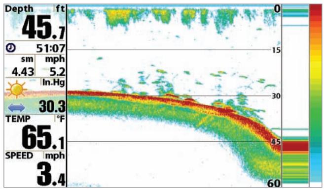
Default Sonar View
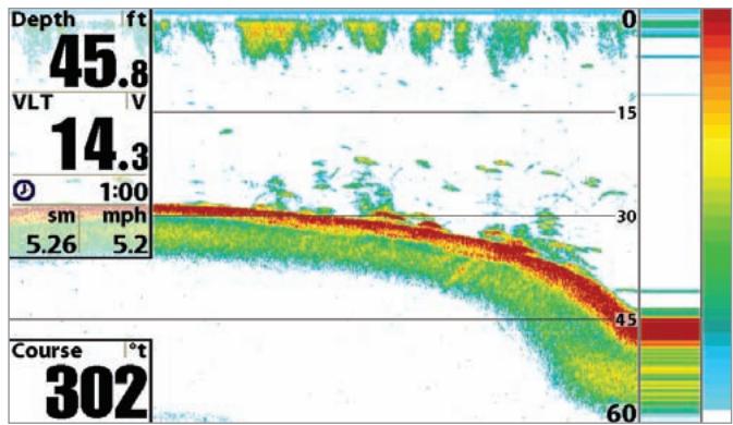
Customized Sonar View
To Select Readouts:
- Make sure you are in Advanced User Mode, then highlight Select Readouts on the Setup main menu.
- Use the RIGHT 4-WAY Cursor Control key to initiate this procedure.
- The Select Readouts submenu will appear, showing a list of all Readouts. Use the UP or DOWN Cursor keys to select a particular Readout position, then use the RIGHT or LEFT Cursor keys to change what will be displayed at that position. (Aux. Temperature, Course, Depth, Off, Position, Speed, Temperature, Time, Time+Date, Triplog, Voltage, Water Speed)
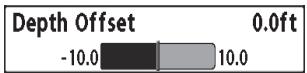
Depth Offset
(Advanced)
Depth Offset will adjust the digital depth readout to indicate depth from the waterline or boats keel. Enter a positive vertical measurement from the transducer to the waterline to read the depth from the waterline. Enter a negative vertical measurement from the transducer to keel to read the depth from the keel. This menu choice is available only when in Advanced User Mode (see Setup Menu Tab: User Mode.)
To change the Depth Offset setting:
- Make sure you are in Advanced User Mode, then highlight Depth Offset on the Setup menu.
- Use the LEFT or RIGHT 4-WAY Cursor Control keys to change the Depth Offset setting. (-10.0 to +10.0 feet or -3 to 3 meters [International models only], Default = 0.0, or Off)
Aux Temp Offset will adjust the aux temperature readout (the temperature on the optional-purchase temperature probe or Temp/Speed accessory) by the amount entered. This menu choice is available only when in Advanced User Mode (see Setup Menu Tab: User Mode.)
To change the Aux Temp Offset setting:
- Make sure you are in Advanced User Mode, then highlight Aux Temp Offset on the Setup menu.
- Use the LEFT or RIGHT 4-WAY Cursor Control keys to change the Aux Temp Offset setting. (-10.0 to +10.0 degrees, Default = 0)
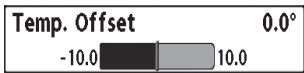
Temp Offset
(Advanced)
Temp Offset will adjust the temperature readout by the amount entered. This menu choice is available only when in Advanced User Mode (see Setup Menu Tab: User Mode.)
To change the Temp Offset setting:
- Make sure you are in Advanced User Mode, then highlight Temp Offset on the Setup menu.
- Use the LEFT or RIGHT 4-WAY Cursor Control keys to change the Temp Offset setting. (-10.0 to +10.0 degrees, Default = 0.0, or Off)
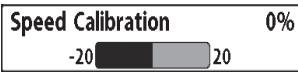
Speed Calibration
(Advanced, with Speed paddlewheel only)
Speed Calibration will adjust the speed readout by the percentage entered, and will appear in the menu if a Speed accessory is connected and the paddlewheel has moved at least once, when the unit is in Advanced User Mode (see Setup Menu Tab: User Mode.)
To change the Speed Calibration setting:
- Make sure you are in Advanced User Mode, then highlight Speed Calibration on the Setup menu.
- Use the LEFT or RIGHT 4-WAY Cursor Control keys to change the Speed Calibration setting. (-20% to +20%, Default = 0%)


Local Time Zone selects your time zone in reference to the time reported by the GPS receiver when Time+Date is selected as a Digital Readout on the Sonar View (see Select Readouts). This menu choice is available only when in Advanced User Mode (see Setup Menu Tab: User Mode.)
To change the Local Time Zone:
- Make sure you are in Advanced User Mode, then highlight Local Time Zone on the Setup menu.
- Use the LEFT or RIGHT 4-WAY Cursor Control keys to change the Local Time Zone (Default = EST [UTC-5] - Eastern Standard Time).
Daylight Saving Time
Off
Daylight Saving Time
(Advanced)
Daylight Saving Time adjusts the time display to account for local Daylight Saving Time. Selecting On adds one hour to the time display adjusted for your local time zone. Selecting Off leaves the time display as adjusted for your local time zone. This menu choice is available only when in Advanced User Mode (see Setup Menu Tab: User Mode.)
To change the Daylight Saving Time setting:
- Make sure you are in Advanced User Mode, then highlight Daylight Saving Time on the Setup menu.
- Use the LEFT or RIGHT 4-WAY Cursor Control keys to turn Daylight Saving Time On or Off. (Off, On, Default = Off)
Position Format
dd'mmm
Position Format
(Advanced)
Position Format selects the format of the latitude and longitude position display. This menu choice is available only when in Advanced User Mode (see Setup Menu Tab: User Mode.)
To change the Position Format setting:
- Make sure you are in Advanced User Mode, then highlight Position Format on the Setup menu.
- Use the LEFT or RIGHT 4-WAY Cursor Control keys to change the Position Format. (dd.ddddd°, dd'mm.mm', or dd'mm'ss", Default = dd'mm.mm')
Time Format
12-Hour
Time Format
(Advanced, International only)
Time Format changes the time format used by the unit This menu choice is available only when in Advanced User Mode (see Setup Menu Tab: User Mode.) International models only. Time Format selects a 12 hour or 24 hour format for the time of day displayed when Time + Date is selected as a Digital Readout on the Sonar View (see Select Readouts).
To change the Time Format:
- Make sure you are in Advanced User Mode, then highlight Time Format on the Setup menu.
- Use the LEFT or RIGHT 4-WAY Cursor Control keys to change the Time Format. (12 hour, 24 hour, Default = 12 hour)
Date Format
mm/dd/yy
Date Format
(Advanced, International only)
Date Format changes the date format used by the unit This menu choice is available only when in Advanced User Mode (see Setup Menu Tab: User Mode.) International models only. Date Format selects the format for the date display when Time + Date is selected as a Digital Readout on the Sonar View. (see Select Readouts).
To change the Date Format:
- Make sure you are in Advanced User Mode, then highlight Date Format on the Setup menu.
- Use the LEFT or RIGHT 4-WAY Cursor Control keys to change the Date Format. (mm/dd/yy, dd.mm.yy or yy.mm.dd, Default = mm/dd/yy)
Digits Format allows you to add a tenth decimal place to readouts such as Temperature and Depth. The format can be changed to small format, large format or no format. This menu choice is available only when in Advanced User Mode (see Setup Menu Tab: User Mode.)
To change the Digits Format setting:
- Make sure you are in Advanced User Mode, then highlight Digits Format on the Setup menu.
- Use the LEFT or RIGHT 4-WAY Cursor Control keys to change the Digits Format setting. (Small tenths, Large tenths, No tenths, Default = Small tenths)
NMEA Output turns the NMEA output on or off. This menu choice is available only when in Advanced User Mode (see Setup Menu Tab: User Mode.)
The following NMEA sentences are output:
DPT-Depth
MTW - Water Temperature
GLL - Lat/Lon Position
GGA-GPS Fix Data
RMC - Recommended Minimum Specific GNSS Data
VTG - Course Over Ground and Ground Speed
ZDA - Time and Date
When navigating, the following NMEA sentences are also output:
APB - Autopilot Sentence B
BWR - Bearing and Distance to Waypoint
RMB - Recommended Minimum Navigation Info
To turn NMEA Output on or off:
- Make sure you are in Advanced User Mode, then highlight NMEA Output on the Setup menu.
- Use the LEFT or RIGHT 4-WAY Cursor Control keys to change the NMEA Output to On or Off (Off, On, Default = Off).
Sonar
Sonar deactivates Sonar and removes the Sonar Views from the view rotation.
To turn Sonar on or off:
- Highlight Sonar on the Setup menu.
- Use the LEFT or RIGHT 4-WAY Cursor Control keys to change the Sonar to On or Off (Off, On, Default = On).
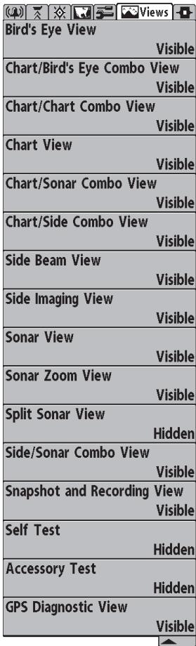
Views Menu
Views Menu Tab
From any view, press the MENU key twice to access the tabbed Main Menu System, then press the RIGHT 4-WAY Cursor Control key until the Views tab is selected. This menu tab allows you to set the available views to either hidden or visible in the view rotation. The view will be removed from the view rotation if it is set to Hidden and will be displayed in the view rotation if it is set to Visible.
The following views are available:
Bird's Eye View
Chart/Bird's Eye Combo View
Chart/Chart Combo View
Chart View
Chart/Sonar Combo View
Chart/Side Combo View
Side Imaging View
- Sonar View
- Sonar Zoom View
- Split Sonar View
Side/Sonar Combo View
- Snapshot and Recording View
- Side Beam View (only with optional-purchase QuadraBeam PLUS™ transducer)
Self Test
- Accessory Test
GPS Diagnostic View.
To Change the View Status of Any View:
- Highlight the View main menu tab.
- Use the UP or DOWN 4-WAY Cursor Control keys to select a View.
- Use the LEFT or RIGHT 4-WAY Cursor Control keys to change the status of the view from Hidden to Visible or vice versa.
Accessories Menu Tab
From any view, press the MENU key twice to access the tabbed Main Menu System, then press the RIGHT cursor key until the Accessories tab is selected.
If no accessories are attached to the Accessory Bus, no accessory menu choices will appear under the Accessories tab, only the Screen Snapshot menu choice. If an accessory is attached, however, additional menu choices that support the accessory will be added automatically. See the Operations Manual that comes with your accessory for detailed information.
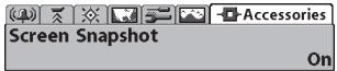
Accessories Menu (no accessories attached)
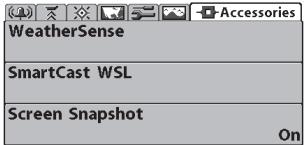
Accessories Menu (with accessories attached)
NOTE: Accessories to enable WeatherSense® and the SmartCast® Wireless Sonar Link (WSL) require separate purchases. You can visit our website at www.humminbird.com or contact our Customer Resource Center at 1-800-633-1468 for additional details.
Screen Snapshot

Using Screen Snapshot
Screen Snapshot activates the screen
snapshot function. When Screen Snapshot is enabled, pressing the MARK key creates a saved screen capture on the optional-purchase MMC/SD card installed in your unit's card slot. All menus, dialog boxes, warnings and messages are captured and saved automatically.
Once you have created a screen capture, a screen capture thumbnail is added to the Snapshot and Recording View, and is available to view at a later date. See the full-sized image by highlighting a thumbnail (using the Up or Down 4-Way Cursor keys), then using the Right 4-Way Cursor key to view the full image. A border around the full-size screen snapshot indicates that it is just a screen snapshot, not a "live" view. You can delete the highlighted image, or all images, by selecting a thumbnail and using Delete Image, or using Delete All Images from the Snapshot and Recording X-Press™ menu. You can view these captures on the Snapshot and Recording View, which shows any existing thumbnails of the screen captures, along with any icons representing sonar recordings.
NOTE: You must have an optional-purchase MMC/SD card installed for the Screen Snapshot feature to work.
NOTE: If you use your MMC/SD card in two different Fishfinder units that have different screen sizes, the recordings made on one unit will still be present on the card, but will be represented by the Unavailable icon (circle with a slanted line through it) on the Snapshot and Recording View on the other unit.
To turn Screen Snapshot on or off:
- Highlight Screen Snapshot on the Accessories main menu.
- Use the LEFT or RIGHT 4-WAY Cursor Control keys to turn Screen Snapshot On or Off (Off, On, Default = Off).
To make a screen snapshot (Screen Snapshot must be enabled):
- Make sure you have installed an optional-purchase MMC/SD card into your card slot.
- From any view you want to capture, press the MARK key. When you start a screen capture, you will see a message that a waypoint has been created at the point where your cursor is on the screen, and the screen will freeze while the snapshot is being saved to the MMC/SD card. A status dialog box will appear that shows the progress of the save as a percentage, and that displays the numbered file name assigned to the .BMP file that is being created.
NOTE: For more information, see Snapshot and Recording View and Snapshot and Recording X-Press™ Menu.
NOTE: Navigation is not affected by the Screen Snapshot feature. Also, if Screen Snapshot is enabled but there is no GPS receiver connected, pressing the MARK key will capture the screen image and display an error saying that a GPS position fix is required to create a waypoint.
NOTE: The speed of the capture depends on the type of card you use; in general, SD cards capture the screen faster than MMC cards do.
To view screen snapshots:
- Make sure that the optional-purchase MMC/SD card used to capture the screen is installed in your card slot.
- Press the VIEW key until you see the Snapshot and Recording View.
- You can scroll through the whole list of captures in this view using the 4-WAY Cursor keys. Highlight a thumbnail (using the Up or Down 4-Way Cursor keys), then use the Right 4-Way Cursor key to view the full image. A border around the full-size screen capture indicates that it is just a screen capture, not a "live" view. You can delete the highlighted image, or all captured images, using the Snapshot and Recording X-Press™ menu. (See Snapshot and Recording X-Press™ menu: Delete Image and Delete All Images for more information).
NOTE: When you highlight a snapshot thumbnail, the amount of room remaining on the SD card will be displayed.
NOTE: The waypoints that are created by a snapshot have the same name as the file and use a custom waypoint icon. Snapshot filenames begin with the letter "S".
NOTE: You may view data files associated with each screen snapshot by removing the MMC/SD card from your unit and installing it in your optional-purchase MMC/SD card reader connected to a PC. Use Windows Explorer to see the contents of your MMC/SD card; you will notice that a .DAT (may show up as .TXT) file is created for every .BMP screen capture; this data file includes the thumbnail view, and is required in order to be able to view the screen snapshot from your unit, so don't delete these files.
Troubleshooting
Before contacting the Humminbird® Customer Resource Center, please read the following section. Taking the time to review these troubleshooting guidelines may allow you to solve a performance problem yourself, and therefore avoid sending your unit back for repair.
900 Series™ Doesn't Power Up
If your 900 Series™ doesn't power up, use the Installation Guide that also comes with it for specific confirmation details, making sure that:
- the power cable is properly connected to the 900 Series™ control head,
- the power cable is wired correctly, with red to positive battery terminal and black to negative terminal or ground
the fuse is operational - the battery voltage of the power connector is at least 10 Volts.
Correct any known problems, including removing corrosion from the battery terminals or wiring, or actually replacing the battery if necessary.
900 Series™ Defaults to Simulator with a Transducer Attached
A connected and functioning transducer will cause the newly-started 900 Series™ to go into Normal operating mode automatically. If, when you power up the 900 Series™, it goes into Simulator mode automatically, even though a transducer is already connected, this means that the control head is not detecting the transducer. Perform the following troubleshooting tasks:
- Using the Installation Guide that also comes with your 900 Series™, check to make sure that the transducer cable is securely connected to the 900 Series. Reconnect if necessary, and power up the 900 Series™ again to see if this fixes the problem.
- Replace the non-functioning transducer with a known good transducer if available and power up the control head again.
- Check the transducer cable. Replace the transducer if the cable is damaged or corroded.
Display Problems
There are several main conditions or sources of possible interference that may cause problems with the quality of the information displayed on the control head. Look in the following table for some symptoms of display problems and possible solutions:
| Problem | Possible Cause |
| The control head loses power at high speeds. | If the power output of your boat's engine is unregulated, the control head may be protecting itself using its over-voltage protection feature. Make sure the input voltage does not exceed 20 Volts. |
| When the boat moves at higher speeds, the bottom disappears or suddenly weakens, or the display contains gaps. | The transducer position may need to be adjusted. A mix of air and water flowing around the transducer (cavitation) may be interfering with the interpretation of sonar data. See your Installation Guide for suggestions on adjusting the transducer position. |
| Electrical noise from the boat's engine may be interfering with sonar reception. See Finding the Cause of Noise for more information. | |
| There are no fish detected, even when you know they are in the water under the boat, or sonar readings seem weak or faulty. | Sonar readings may be affected if the transducer is not positioned correctly (i.e. mounted at an angle, not straight down), or there is some kind of mechanical interference, either because it is mounted inside a hull that is too thick for proper sonar transmission, the bond between the transducer and the hull is not airtight, or because the transducer is dirty. Check with your Installation Guide for guidance on re-positioning the transducer, and make sure the transducer is clean. |
| Low battery voltage may be affecting the power of signal transmission. | |
| Electrical noise from the boats engine may be interfering with sonar reception. See Finding the Cause of Noise for more information. |
Finding the Cause of Noise
Electrical noise usually affects the display with many black dots at high speeds, and high sensitivity readings. One or more of the following sources can cause noise or interference:
| Possible Source of Noise | Isolation |
| Other electronic devices | Turn off any nearby electronic devices to see if the problem goes away, then turn them on one at a time to see if the noise re-appears. |
| The boat's engine | To determine whether the boat's engine is the source of the noise, increase the RPMs while the boat is in neutral and stationary to see if the noise increases proportionately; if noise appears when you rev the engine, the problem could be the spark plugs, alternator, or tachometer wiring. Replace the spark plugs with resistor plugs, install an alternator filter, or route the control head power and transducer cables away from the engine wiring. |
| Cavitation from the boat's propeller | Turbulence created by the propeller can cause noise; make sure the transducer is mounted at least 15" (38 cm) from the propeller, and that the water flows smoothly over the face of the transducer at all times. |
1-Year Limited Warranty
We warrant the original retail purchaser that products made by Humminbird® have been manufactured free from defects in materials and workmanship. This warranty is effective for one year from the date of original retail purchase. Humminbird® products found to be defective and covered by this warranty will be replaced or repaired free of charge at Humminbird's option and returned to the customer freight prepaid. Humminbird's sole responsibility under this warranty is limited to the repair or replacement of a product that has been deemed defective by Humminbird®. Humminbird® is not responsible for charges connected with the removal of such product or reinstallation of replaced or repaired parts.
This warranty does not apply to a product that has been:
- Improperly installed;
- Used in an installation other than that recommended in the product installation and operation instructions;
- Damaged or has failed because of an accident or abnormal operation;
- Repaired or modified by entities other than Humminbird.
Please retain your original receipt as a proof of the purchase date. This will be required for in-warranty service.
THIS WARRANTY IS EXPRESSLY IN LIEU OF ANY OTHER WARRANTYES, OBLIGATIONS OR LIABILITIES ON THE PART OF HUMMINBIRD® AND WILL BE THE CUSTOMER'S EXCLUSIVE REMEDY, EXCEPT FOR ANY APPLICABLE IMPLIED WARRANTYES UNDER STATE LAW WHICH ARE HEREBY LIMITED IN DURATION TO ONE YEAR FROM THE DATE OF ORIGINAL PURCHASE. IN NO EVENT WILL HUMMINBIRD® BE LIABLE FOR ANY INCIDENTAL OR CONSEQUENTIAL DAMAGES FOR BREACH OF ANY EXPRESS OR IMPLIED WARRANTY RELATING TO THE PRODUCTS.
Some states do not allow limitations on an implied warranty, or the exclusion of incidental or consequential damages, so the above exclusions may not apply to you. You may also have other rights, which vary from state to state.
Humminbird® Service Policy
Even though you'll probably never need to take advantage of our incredible service policy, it's good to know that we back our products this confidently. We do it because you deserve the best. We will make every effort to repair your unit within three business days from the receipt of your unit at our factory. This does not include shipping time to and from our factory. Units received on Friday are typically shipped by the following Wednesday, units received Monday are typically shipped by Thursday, etc.
All repair work is performed by factory-trained technicians to meet exacting factory specifications. Factory-serviced units go through the same rigorous testing and quality control inspections as new production units.
After the original warranty period, a standard flat rate service charge will be assessed for each repair (physical damage and missing parts are not included).
Any repairs made after the original warranty will be warranted for an additional 90 days after service has been performed by our factory technicians. You can contact our Customer Resource Center or visit our website to verify the flat rate repair fee for your product (visit the Product Support section):
http://www.humminbird.com
We reserve the right to deem any product unserviceable when replacement parts are no longer available or impossible to obtain. This Service Policy is valid in the United States only. This applies only to Humminbird® products returned to our factory in Eufaula, Alabama. This Service Policy is subject to change without notice.
Returning Your Unit for Service
Before sending your unit in for repair, please contact the factory, either by phone or by email, to obtain a Repair Authorization Number for your unit. Please have your product model name and serial number available before calling the factory. If you contact the factory by e-mail, please include your product model name and serial number in the e-mail, and use Request for Repair Authorization Number for your e-mail subject header. You should include your Repair Authorization Number in all subsequent communications about your unit.
For IN-WARRANTY service, complete the following steps:
- Obtain a Repair Authorization Number from the Humminbird® Customer Resource Center.
- Tag product with your name, street address, phone number and your assigned Repair Authorization Number.
- Include a brief written description of the problem.
- Include a copy of your receipt (to show proof and date of purchase).
- Return product freight prepaid to Humminbird®, using an insured carrier with delivery confirmation.
For OUT-OF-WARRANTY service, complete the following steps:
- Obtain a Repair Authorization Number from the Humminbird® Customer Resource Center.
- Include payment in the form of credit card number and expiration date, money order or personal check. Please do not send cash.
- Tag product with your name, street address, phone number and your assigned Repair Authorization Number.
- Include a brief written description of the problem.
- Return product freight prepaid to Humminbird®, using an insured carrier with delivery confirmation.
900 Series™ Accessories
Accessories customize the 900 Series™ to your needs and enable you to stay on the edge of new technology. When an accessory is connected to the 900 Series™, additional menus and readouts are added automatically to the Main Menu System. Accessories available today that are supported by your 900 Series™ include:
QuadraBeam PLUS™ transducer: purchase and connect the QuadraBeam PLUS™ transducer to your 900 Series™ Fishing System to access specialized QuadraBeam PLUS™ functions such as two 45^ fan-shaped 35^ 455 kHz Side Structure locating sonar beams to spot fish, bait and structure to the left and right of the boat over an area of the bottom that's always equal to twice your depth, for a continuous 90^ of uninterrupted side to side coverage to 160 feet.
WeatherSense® Fishing Condition Monitor: purchase and plug in the WeatherSense® accessory to your 900 Series™ to obtain barometric pressure readouts and trend data in real time.
GPS Connection Cable: purchase the GPS Connection Cable in order to connect a handheld or other NMEA* GPS-compatible device that you may already own to your 900 Series™.
*NMEA 0183 is a National Marine Electronics Association standard for data communication.
Wireless Sonar Link (WSL): purchase the Wireless Sonar Link (WSL) accessory to receive remote sonar signals from a SmartCast® Remote Sonar Sensor (RSS). Radio signals from the RSS are received by the WSL and are transmitted over the Accessory Bus to the 900 Series™.
PC Connect Cable: Purchase the PC Connect Cable to connect the 900 Series™ Fishing System to a PC in order to upload product software updates and new features obtained from www.humminbird.com. This accessory requires the MSWindows-compatible HumminbirdPC™ software downloaded from our website to your PC in order to communicate with the 900 Series™ Fishing System.
Universal Sonar 2: Your 900 Series™ Fishing System supports Universal Sonar 2, a state-of-the-art, integrated and protected transducer that is built into the lower unit of Minnkota trolling motors. With Universal Sonar 2, all wiring is concealed inside the indestructible composite shaft—out of sight and out of harm's way, with no clamps, ties, or exposed wires. Universal Sonar 2 features new temperature sensing and the performance of DualBeam PLUS™ technology (available with all Humminbird® DualBeam PLUS™ models). An expanded view and greater bottom detail gives you a totally new perspective of the water below, along with optimal sonar performance to help you find fish.
Downriggers are the key to catching fish you otherwise couldn't even touch. And now Humminbird's CannonLink™ Downrigger Controller makes operation of up to six Cannon™ Mag 20 DT or Mag 20 DT/HS downriggers incredibly easy. Using the controls on your Fishing System, deploy or retrieve downriggers, hold a specific distance off the bottom, cycle downriggers between two depths, and adjust the Positive Ion Control. Even see temperature and water clarity at depth and speed at the ball right on-screen when using the Cannon™ Speed-n-Temp. You'll never be shorthanded again, just make adjustments from the helm, while your mate rigs the lines and brings in the fish!
With the new InterLink™ Network Connection, you can now share GPS position, waypoints, routes and your current track between two Humminbird® Fishing Systems in real time. Mark a waypoint at the console, and it's instantly available on the second unit. No matter where you're at on the boat, you'll have access to your critical fishing and navigation information. Plus, daisy chain InterLink™ with other System Modules and you'll have a network that lets you share digital data around the boat. It's a simply, clearly, better networking solution!
Be sure to check out our website www.humminbird.com for additional new and exciting accessories to grow your 900 Series™.
NOTE: Each accessory requires a separate purchase. You can visit our website at www.humminbird.com or contact our Customer Resource Center at 1-800-633-1468 for additional details.
Specifications
Depth Capability 1500 ft (500 m)
Power Output 500 Watts (RMS); 4000 Watts (Peak-To-Peak)
Operating Frequency Dual Beam: 200 kHz and 83 kHz DualBeam PLUS™ Side Imaging: 455 kHz/800 kHz
Area of Coverage Dual Beam: .60° @ -10 dB in 83 kHz and 20° @ -10 dB in 200 kHz Side Imaging: .455 kHz: (2) 84° @ -10 db (180° Total Coverage) 800 kHz: (2) 70° @ -10 db (160° Total Coverage)
Target Separation 2 1/2 Inches (63.5 mm)
Power Requirement 10-20 VDC
LCD 480 V x 800 H; 8" Diagonal Color TFT
Transducer XHS 9 HDSI 180 T
Transducer Cable Length 20 ft (6 m)
NOTE: Product specifications and features are subject to change without notice.
NOTE: Humminbird® verifies maximum stated depth in saltwater conditions, however actual depth performance may vary due to transducer installation, water type, thermal layers, bottom composition and slope.
POLICY ON ENVIRONMENTAL COMPLIANCE: It is the intention of Humminbird® to be a good corporate citizen and comply and meet all known and applicable environmental regulations in the areas and countries where our products are sold. We will promote and implement environmentally sound processes in support of national and international regulations.
ROHS STATEMENT: Product designed and intended as a fixed installation or part of a system in a vessel may be considered beyond the scope of Directive 2002/95/EC of the European Parliament and of the Council of 27 January 2003 on the restriction of the use of certain hazardous substances in electrical and electronic equipment.
WEEE STATEMENT: Product designed and intended as a fixed installation or part of a system in a vessel may be considered beyond the scope of Directive 2002/96/EC of the European Parliament and of the Council of 27 January 2003 on waste electrical and electronic equipment (WEEE).
CALIFORNIA PROPOSITION 65 STATEMENT: Lead in cable jackets and boots is restricted to 300 parts per million or less as determined by ICP-AES test methods.
Alarm, Depth: Depth Alarm is a user-controllable, audible alert that sounds when depth is less than or equal to the setting.
Alarm, Temperature: Temperature Alarm is a user-controllable, audible alert that sounds when the water surface temperature equals the setting.
Backlight: Backlight is a user-controllable illumination for the LCD for night and low light use.
Beam (Sonar Beam): A sonar beam is the wide, cone-shaped projection of sound waves formed as sound travels underwater. See Cone Angle.
Big Digits View: Big Digits View is a Humminbird® feature that displays the sonar graph and enlarged digital readouts for easy reading from a distance. This is a great tool when monitoring the digital depth is important - such as with higher boat speeds, or when viewing the unit from a distance. When speed input is available, the Big Digits View also shows the TripLog. See TripLog.
Bottom Black: Bottom Black is a Humminbird® feature that "fills in" the area of the display below the bottom contour. Bottom Black is preferred by some anglers because of its high contrast and easy readability, even though it can obscure bottom hardness information.
Bottom Contour: Bottom Contour is the profile of the bottom graphed to the display as the depth changes.
Bottom Hardness: Bottom Hardness is the density (or composition) of the bottom, which can often be determined by interpreting the main sonar return. Varying levels of hardness can be determined by interpreting the "thickness" of the sonar return. Hard returns appear thin and black, softer returns appear thicker and less black. It is important to note that a sonar return from a sloping bottom can have the appearance of a softer bottom.
Cavitation: Cavitation is the effect of air bubbles created as the propeller rotates and the boat moves through the water.
Chart Speed: Chart Speed is a user-controllable feature that sets the speed at which sonar information moves across the display. A faster setting displays sonar information from more pings and shows more detail, but the information moves quickly across the display: a slower setting permits viewing of more sonar history, but does not display as much detail. The best setting is often the user's personal choice.
Cone Angle: The cone angle is the angular measurement of the sonar beam at a specific dB down point (i.e. -10 dB). See dB Down Point.
Customizable Digital Readouts: Customizable Digital Readouts is a Humminbird® feature that permits the user to select the specific digital information that appears in the main Sonar view (i.e. Speed, Temperature, Barometric Pressure, TripLog, etc.)
Dead Zone: The dead zone is the area of the sonar beam that receives the sonar signal after the main bottom return. Fish and other objects close to the bottom that fall within the dead zone will probably not be visible in the sonar beam. Precision sonar beams, such as the Humminbird® 20^ beam, have a smaller dead zone than wider sonar beams.
Decibel: A Decibel is the measurement for sound pressure level, or "intensity" of the sonar return. See dB Down Point.
dB Down Point: The dB Down Point is the standard decibel level at which the sonar cone angle is measured, and is written as "@ -10 dB" or "@ -3 dB". Measurements at smaller down points (bigger negative numbers) indicate that the less intensive sonar signals are being used for the measurement.
Display, FSTN: FSTN is an acronym for Film Super-Twist Nematic. FSTN is a monochrome display technology characterized by black, high-contrast pixels. All monochrome fixed mount Humminbird® products use FSTN technology.
DualBeam PLUS™: DualBeam PLUS™ is a Humminbird® sonar configuration that uses two sonar beams simultaneously, and combines the information from both beams into one view by overlapping the data on-screen, or shows each beam individually side by side, or permits each beam to be viewed individually full screen.
Feature Memory: Feature Memory is a Humminbird® feature that retains the user's menu settings in permanent memory. Settings are retained even when the unit is powered off indefinitely.
Fish Arch: A Fish Arch is the apparent "arch" that appears on the display when any object moves through the sonar cone. The arch results from a gradual decrease in distance to an object as it moves into the sonar cone. The distance to an object changes due to the conical shape of the sonar beam, which causes the distance to be greater at the edges of the beam than at the center of the beam. When this distance change is graphed on the display, an arch appears.
Fish ID^+^TM : Fish ID^+^TM is a Humminbird® feature that uses advanced sonar processing algorithms to determine if a detected object is likely to be a fish. When the sonar signal from an object meets strict parameters, the unit draws a Fish Symbol (or icon) and the digital depth of the target. On DualBeam and DualBeam PLUS^TM units, fish detected in the narrow center beam are shown as shaded symbols, and fish detected in the wider beam are shown as hollow symbols.
Fish Symbol: A Fish Symbol is the graphic that is displayed on the screen when Fish ID + ^TM determines that a sonar return is likely to be a fish. See Fish ID+ ^TM .
Freeze Frame: Freeze Frame is a Humminbird® feature that pauses the sonar scrolling so that the image on screen can be studied with greater detail. See Instant Image Update.
Frequency: Frequency is a measure of the number of sound wave cycles per second of a sound impulse transmitted underwater. A typical frequency for fishfinders is 200kHz , which offers a good balance of performance under many conditions. Lower frequencies, such as 50kHz , are capable of penetrating to greater depths, but with less resolution. Higher frequencies, such as 455kHz , offer greater resolution, but are limited in depth performance. Humminbird uses a variety of frequencies that are optimized for specific applications.
Grayscale: Grayscale is the use of varying shades of gray to represent the strength of the sonar signal on the display, and is a very intuitive method of presenting information. Traditionally, the strongest sonar signals are represented in black, and progressively weaker signals are represented in progressively lighter shades of gray.
Grayscale, Inverse: Inverse Grayscale is a Humminbird® feature that reverses the correlation of sonar signal strength and the shade of gray typically used to represent it. The strongest sonar signals are represented by "white", and progressively weaker signals are represented in progressively darker shades of gray. While somewhat counter-intuitive, this method makes the sonar images crisp, and has the benefit of enhancing the apparent sensitivity because the weaker signals appear bolder. Inverse grayscale works well in very clear water. Debris-laden water often appears as a lot of clutter on the screen.
Instant Image Update: Instant Image Update is a Humminbird® feature that updates all the sonar information on the display when Sensitivity and a variety of sonar settings (Bottom View, Range, etc.) are modified. This differs from the traditional functionality that only updates the new sonar information collected after the setting change. Instant Image Update permits more accurate fine-tuning of the
display because the user can see the results on the complete sonar graph. When combined with the Freeze Frame feature, the user can adjust and understand the effects of many different sonar settings quickly and easily.
Maximum Depth Menu: The Maximum Depth Menu is a Humminbird® feature that optimizes performance based on the maximum operational depth set by the user. Many Humminbird® units can operate across a very broad depth range (up to 2500 feet) which causes the unit to "look" up to that full depth under some circumstances. Due to the speed of sound in water, this can result in less responsiveness because the unit has to wait for a longer period of time to receive the sonar signal. When the Maximum Depth menu is set to a lower value, the unit only looks up to the setting, which increases the responsiveness of the unit. This is an important feature for anyone operating in shallower depths!
Noise: Noise is unintentional, external sound waves that interfere with the optimal operation of sonar. Noise appears as random "dots" on the display, and is caused by a variety of sources. Electrical noise (from trolling motors, bilge pumps, VHF radios) typically manifests as a consistent dot pattern. Electrical noise can be isolated by selectively turning on and off other electrical devices to determine the source. Often re-routing the power cable, or connecting to an alternative power supply (second battery) can help overcome electrical noise. Hydrodynamic noise (from propeller and/or hull cavitation) has a more random appearance and is generally related to boat speed, so that faster operation results in more noise. Hydrodynamic noise can be overcome by proper transducer installation. Many Humminbird® products have a Noise Filter menu setting that allows the user to clear the screen of noise that is difficult to eliminate.
Pixels: Pixels are the "picture elements", or small square blocks, that make up the image on the LCD. Measured as a vertical by horizontal number (i.e. 640V× 320H ), this key specification typically indicates the quality of resolution.
In fishfinders, the total resolution (vertical multiplied by horizontal) is often less important than the "Vertical Pixel" resolution. See Pixels, Vertical.
Pixels, Vertical: Vertical Pixels are a number of vertical picture elements in a single column on an LCD display. A greater number of vertical pixels provide finer resolution of targets detected by sonar. Essentially, a vertical distance (the depth), when divided by a larger number, breaks that distance into smaller samples, each representing a smaller area and thus providing more detail. In fishfinders, vertical pixels are more critical than horizontal pixels because the horizontal axis of the display represents time, or history. Sonar information on the horizontal axis can vary greatly, depending on boat speed and the Chart Speed setting. A greater number of horizontal pixels show more sonar history that the boat has passed through. On many models, Humminbird® provides the most vertical pixels to provide a better display resolution. See Chart Speed and Pixels.
Power Output: Power output is the amount of sound energy emitted into the water by the sonar transmitter. Power output is measured using either RMS (Root Mean Square) or P-T-P (Peak-to-Peak) measurement systems. Either method is acceptable, but it is important, when comparing power outputs, to make sure that the same measurement system is being used for both outputs, because P-T-P numbers are 8 times higher than RMS numbers. Greater power output allows the sonar signal to penetrate through weeds and thermoclines, reach deeper depths and operate more effectively in noisy environments, such as when the boat is running at high speed.
Pulse Width (Pulse Length): Pulse Width is the length of time that a sonar sound burst is transmitted into the water. Shorter pulse widths provide better target separation, but cannot travel to great depths. Longer pulse widths provide better depth penetration, but result in poorer target separation. Humminbird® varies pulse width based on depth to optimize both target separation and depth performance. See Target Separation.
QuadraBeam PLUS™: QuadraBeam PLUS™ is a Humminbird® sonar configuration that uses four sonar beams for a more detailed bottom image. QuadraBeam PLUS™ uses the DualBeam PLUS™ configuration for downlooking, and also adds two additional beams to look to the left and right. The sonar beams pointing to the left and right provide the ability to spot fish and structure over a wide 90^ area, and to identify on which side of the boat they are located. See DualBeam PLUS™.
Quick Disconnect Mount: The Quick Disconnect Mounting system is an exclusive Humminbird® feature that permits the unit to be easily removed from the mounting base by pressing a release button, and re-installed by simply snapping it back into place. All cable connections are made when installing, so that no separate wiring connections are required. Additionally, the mount offers 90^ tilt and 360^ swivel capability to adjust the viewing angle of the unit as you move about the boat.
Real Time Sonar: Real Time Sonar is a Humminbird® technology that delivers ultrafast sonar transmitter/receiver operation and results in a more detailed instantaneous view of what is under the boat. The Real Time Sonar window is a vertical band at the right side of the display that shows the instantaneous sonar return from the transducer at a particular instant. The RTS® Window menu option permits the user to adjust the window to show the full sonar signal return, or just a narrower band that indicates intensity using grayscale. Real Time Sonar relies on very fast Sonar Update Rate (Ping Speed). See Sonar Update Rate.
Receiver: See Transmitter.
Second Return: The Second Return is a term that describes the appearance of a second sonar return below the primary sonar return (bottom contour) at exactly twice the true depth. The second return is caused by the same sonar energy bouncing off the bottom once, rebounding to the water surface and then traveling back down to the bottom to be reflected again. Second returns are more common
in shallow water and over hard bottoms; it is actually possible to see a third sonar return under some circumstances. The second return provides useful information to help determine bottom hardness, as areas with harder bottoms will generally create a second return. The second return can be used as a guide to set Sensitivity when in shallower water.
Sensitivity: Sensitivity is a user feature that adjusts the sensitivity of the sonar system to show more or less detail in the water. Higher sensitivities are often preferred, however, when the water contains debris (silt, storm debris, etc.) and it can be difficult to pick out targets. Conversely, if sensitivity is set too low, relevant targets may be missed.
SONAR: SONAR is the acronym for SOund and NAvigation Ranging. Sonar technology uses precision sound bursts transmitted underwater to determine the distance and other attributes of objects in the water. Distance can be determined because the speed of sound in water is constant, and the time for the signal to return is measured. Sound also travels very quickly underwater, making sonar a responsive, cost-effective tool. Sonar is the basic technology behind all recreational and commercial fishfinding and depthfinding devices.
Sonar Echo Enhancement: Sonar Echo Enhancement is a Humminbird® feature that describes the high degree of sonar sensitivity achieved through a combination of transmitter/receiver and software algorithms. The result of Sonar Echo Enhancement is to display virtually everything in the water that is of interest to the angler, including bait fish, game fish, thermoclines, weed beds, subtle structure, and more.
Sonar Update Rate: Sonar Update Rate is the number of times per second that the transmitter/receiver sends and receives sonar signals. A very fast sonar update rate collects more information and provides a more detailed image of the bottom, fish
and structure. Many Humminbird® units operate at up to 40 times per second when in single frequency operation. Due to the limitation of the speed of sound in water, the update rate begins to slow as depth increases to deeper than 50 feet. In very shallow water (less than 10 feet), however, update rates as much as 60 times per second can be achieved.
Speed: Speed is the rate at which the boat moves through the water. Boat speed can be measured as Speed Over Ground or Speed Through Water. Speed Over Ground is provided by GPS, and is the measurement of the boats progress across a given distance. Speed Through Water is provided by a speed paddlewheel, and is the measurement of the flow past the boat, which may vary depending on current speed and direction. Speed Through Water is most critical for anglers using downriggers, as it impacts the running depth of the down riggers. Speed Over Ground is optimal for navigation, as accurate destination times can be derived from this measurement. Humminbird® products allow for input and display of both sources.
Structure: Structure is a general term for objects on the bottom that present a discontinuity and are a likely attractor for fish. This includes bottom contour features (drop-offs, humps, and holes), standing structure (stumps, timbers, brush piles) and a wide range of other potential objects (sunken boats, reefs). Humminbird® units excel at showing structure with great detail over a wider area due to unique sonar configurations developed for the angler.
Structure ID®: Structure ID® is a Humminbird® feature that describes the traditional grayscale method of presenting sonar information. See Grayscale.
Surface Clutter: Surface Clutter is a phenomenon where sonar returns are reflected off of tiny objects near the surface of the water, including algae and even
air bubbles. Typically, saltwater environments have significantly greater surface clutter than freshwater due to continuous wind and wave action that causes aeration at the surface. The Surface Clutter menu provides manual control to bias the default settings under extreme conditions.
Target Separation: Target Separation is the measurement of minimum distance that a fishfinder needs to be able to recognize two very close objects as two distinct targets (i.e. two fish hanging very close, or a fish hanging very close to structure). Humminbird® fishfinders provide a very good 2 1/2 inches of target separation in shallower than 100 feet of depth. Target separation decreases as depth increases due to the need for longer Pulse Width to achieve greater depth. See Pulse Width.
Thermoclines: Thermoclines are water layer(s) of distinctly different temperatures that create a sonar reflection due to the density of the differing water temperatures. Typically a thermocline will appear as a continuous band across the display at some distance above the bottom contour. Thermoclines are of interest to anglers because fish will suspend above or below the thermocline as they seek the optimum temperature and oxygen levels.
Time Variable Gain: Time Variable Gain is a processing step applied to the sonar return to "normalize" the data so that objects of equal size (i.e. fish) appear to be the same size, even if they are separated by a good distance. Time Variable Gain is a fundamental attribute of good sonar, but is often promoted as a feature.
Total Screen Update®: A Humminbird® feature that refreshes and updates all the sonar information on the display when a range change occurs. Without Total Screen Update®, only the most recent sonar information would be drawn to the new range, and the old sonar information would continue to scroll off the screen at the old range.
Transducer: The transducer is part of the sonar system, which mounts on the boat and is in contact with the water, that converts the electrical energy from the transmitter into sound energy, and that forms the sonar beam in turn. Internally, the transducer consists of one or more piezo electric disks that expand by very minute amounts to create the sound wave. This element also works in reverse, converting the returned sound energy back into an electrical signal that the receiver interprets. Transducers are available for many specific mounting applications for the boat, such as a transom mount, trolling motor mount, etc. Humminbird offers many sophisticated transducers, often with multiple piezo electric elements designed to form specifically-shaped sonar beams, providing the angler with superior tools for finding and catching fish. See Transmitter and SONAR.
Transmitter: The transmitter and receiver are matched parts of the sonar system that send (transmit) and listen to (receive) the sonar signals, and work in conjunction with the transducer. Humminbird® transmitters have an extremely fast cycling design that can send signals up to 60 times per second, as well as produce the varying levels of power output needed for different depths and conditions. Additionally, the transmitter has the capability to create very precise sonar pulses needed for a high degree of target separation. Humminbird® receivers are extremely sensitive, but within a narrow "bandwidth" to discriminate against noise from external sources. Additionally, the receiver offers a wide "dynamic range" which provides the ability to receive very strong signals alternating with very weak signals, without the strong signal overwhelming the weak signal. See Transducer and Noise.
TripLog: TripLog is a Humminbird® feature that provides an on-screen counter for Elapsed Time, Average Speed and Total Distance traveled, and requires a speed input to activate the feature. TripLog appears on the Big Digits View, and can be reset to zero through the TripLog menu.
TrueArch®: TrueArch® is a Humminbird® feature that provides true fish arches, not artificial arches or symbols. Humminbird® units are capable of producing fish arches due to the wide 60^ sonar beam of DualBeam PLUST™, an extremely sensitive sonar receiver. See Fish Arch.
Viewing Angle: Viewing Angle is an attribute of an LCD that characterizes visibility of the display when viewing from off the central access, such as when standing to the side of the fishfinder. Wider viewing angles are better because the information remains visible even when viewing from the side.
WhiteLine®: WhiteLine® is a Humminbird® feature that highlights the strongest sonar return on the display using a very light gray band. This is preferred by some anglers who have grown accustomed to the feature on paper graph chart recorders.
WideSide®: WideSide® is a Humminbird® sonar configuration used in an optional transducer. WideSide® uses three sonar beams pointing to the left, right and down. Beams pointing to the left and right are effective for spotting fish and structure near the surface or on the bank. The downlooking beam provides depth information directly below the boat.
X-Press™ Menu: X-Press™ Menus are a Humminbird® feature that make the most commonly-used menu selections available with one press of the MENU key. Items that appear on the X-Press™ Menu are related to the current view, and present the most logical choices for that view. Sonar View X-Press™ menus will differ from Chart View X-Press™ menus, etc. X-Press™ menus are one of the principal reasons that Humminbird® products are easier to use.
Zoom: Zoom is a feature that focuses in on a smaller area of the bottom to provide enhanced resolution. With enhanced resolution, the angler can more easily see fish hanging in structure or multiple fish hanging close together. Split screen zoom divides the display into the full range view on the right, and the zoomed view on the left. Humminbird® offers One-Touch® Zoom which allows the zoom feature to be easily accessed from the regular sonar view with just one key press, eliminating the need to use menus to access the feature.
Zoom, Bottom Lock: Bottom Lock Zoom is a feature that focuses on a smaller area just above the bottom to provide enhanced resolution. Unlike regular zoom, it continuously graphs the bottom at a constant point on the display regardless of changes in depth. This "flattens" out the bottom contour, but is effective at showing fish on or near the bottom, and is preferred by many saltwater anglers.
Acquisition Time: The length of time that a GPS receiver typically takes to determine a position from at least three satellites. Humminbird® GPS receivers provide very fast acquisition times (under one minute), permitting users to get out on the water faster.
Alarm, Arrival: The audible alert that sounds when the boat is equal to or less than the alarm setting (25 feet - 3000 feet) from the location of the destination waypoint.
Alarm, Drift: Drift Alarm is an audible alert that sounds when the boat is equal to or over the alarm setting (25 feet - 3000 feet) from the location where the alarm was turned on.
Alarm, Off-Course: Off-Course Alarm is an audible alert that sounds when the boat's distance from the intended Track, (Cross Track Error), is equal to or over the alarm setting (25 feet - 3000 feet). See Track and Cross Track Error.
Altitude: Altitude measures height above sea level. Altitude is a measurement that can be provided by GPS.
Bearing (BRG): Bearing is the direction to a destination waypoint measured in degrees from North (i.e. 321^ , where 000^ is North, 090^ East, 180^ is South, 270^ is West).
Chartplotter: Chartplotter describes a navigation device that shows Present Position on a Map, along with Tracks, Waypoints, and Routes. All Chartplotters are also considered Trackplotters. All Humminbird® GPS Combo units are Chartplotters. See Trackplotter.
Cold Start: Cold Start refers to the procedure that a GPS receiver must perform when it does not have historical information regarding its current location. This procedure typically lasts for several minutes, and may be experienced upon first power up of the receiver, or if the receiver has been moved a great distance.
Course Over Ground (COG): Course Over Ground is the current direction the boat is traveling measured in degrees from North (i.e. 321^ , where 000^ is North, 090^ East, 180^ is South, 270^ is West). When the Course Over Ground is equal to Bearing, the boat is said to be "On Course" and will arrive at the destination in the most efficient manner. COG is often confused with Heading. See Heading.
Cross Track Error (XTE): Cross Track Error is the straight-line distance of the boat from the intended Track. XTE measures how far the boat is off course, and also triggers the Off Course Alarm. See Track.
Differential GPS (DGPS): Differential GPS is a system to improve the position accuracy of the Department of Defense GPS through the use of secondary "correction signals" broadcast from ground stations around the coastal United States and on some inland waterways. These correction signals are provided by the USCG and received by an auxiliary Differential Beacon Receiver (DBR) that connects to the GPS receiver. The advent of WAAS has largely negated the need for the added expense of a DBR in the United States.
Distance To Go: Distance To Go is the straight-line distance between Present Position and the Destination Waypoint. DTG and SOG (Speed Over Ground) are used to calculate Time To Go. See Time to Go and Speed Over Ground.
Estimated Position Error (EPE): Estimated Position Error is a calculation that indicates the potential position inaccuracy the user may experience due to a variety of GPS factors which include satellite position in the sky, signal strength and others factors.
Fix Type: Fix Type indicates whether the GPS receiver is providing 2D fix or 3D fix. A 2D fix requires only three satellites and provides only latitude and longitude. A 3D fix requires four or more satellites, and provides latitude, longitude and altitude.
GPS: GPS is an acronym for Global Positioning System. GPS provides accurate position (latitude, longitude, altitude) information virtually anywhere on the earth through satellite technology and personal receivers on the ground. A series of geosynchronous satellites broadcast a unique signal toward the earth once per second. A GPS receiver, such as that included with many Humminbird® products, receives the signals from these satellites and is able to determine position based on very slight differences in the time each signal is received and the receiver's knowledge of the location of each of the satellites.
Heading: Heading describes the direction the boat is pointing and is measured in degrees (i.e. 321^ , where 000^ is North, 090^ East, 180^ is South, 270^ is West). Due to wind and waves, the boat is often traveling in a slightly different direction than it is heading, and therefore Heading is often confused with Course Over Ground. See Course Over Ground.
Map Datum: A Map Datum refers to a particular survey of the earth's surface that was referenced when creating a chart (i.e. WGS84). Since the earth is not flat, and not even consistently round, a mathematical model must be used to translate coordinates from the sphere of the earth to the flat surface of a chart.
This mathematical model is the Map Datum. Historically, many different Map Datums have been used around the world to create maps; often a reference to the Map Datum can be found in the legend of a paper map. It is important to select the correct Map Datum setting in your fishfinder when comparing GPS position to a paper chart to avoid slight position inaccuracies. Almost all electronic charts use the WGS84 Map Datum and therefore, they do not require setting changes.
MMC: MMC is an acronym for Multi Media Card. An MMC is a postage stamped memory device used to store electronic data such as maps, waypoints, routes and other information. MMC is a very rugged format suitable for the marine environment, but it is not waterproof. The MMC is removable from Humminbird® products, and can be used in a PC that is equipped with an appropriate card reader. MMC is the same format that many digital cameras use. See SD.
North, Magnetic: North is the principle reference point of the compass (i.e. North is 000^ ). Magnetic North relies on the earth's magnetic field to align a metal pointer generally towards True North. However, due to local variations in the earth's magnetic field around the globe, the difference between True North and Magnetic North can be greater than 10^ . See True North.
North, True: North is the principle reference point of the compass (i.e. North is 000^ ). True North uses the axis of the rotation of the earth as the reference for North and is constant for all points on the earth. Most GPS units default to True North as the setting. The GPS heading may vary from the boat compass heading because the compass uses Magnetic North. Humminbird® GPS units provide the option of selecting True or Magnetic readouts by using the North Reference menu. See Magnetic North.
Present Position: Present Position is the current location (latitude, longitude) determined by GPS. The Present Position is indicated on-screen by a directional boat icon if the boat is moving, or a round symbol if the boat is stationary.
Route: A Route is a series of waypoints linked together in a specific sequence to define a navigation path between two points, and saved in the fishfinder's memory. Routes are often used when frequently traveling between two or more locations because it is a faster and more accurate method than repeatedly selecting individual waypoints each time one travels through the same area. Routes consist of a Start Waypoint, an End Waypoint, and a series of waypoints in between. Users can begin navigation at the beginning, the end (to run the route in reverse) or at any waypoint in between. See Waypoint.
SD: SD is an acronym for Secure Digital. An SD card is virtually identical in function to an MMC; however, the speed at which information can be accessed is generally faster, the storage capacity is generally larger, and the card has security features which can be used to prevent extracting the data from the card. SD is the same format that many digital cameras use. See MMC.
Selective Availability: Selective Availability (SA) is a GPS system "feature" that can be implemented by the U.S. Department of Defense (DoD) to degrade the accuracy of GPS positioning information. With SA active, the GPS is accurate to within 100 meters 95% of the time. With SA inactive, the GPS is accurate to within 45 meters 95% of the time. Currently, SA is inactive and the consumer can enjoy the greater precision GPS provides; however, the DoD reserves the right to activate SA at any time.
Speed Over Ground (SOG): Speed Over Ground is the measurement of the boat's progress across a given distance, and is the speed measurement provided by GPS. An alternate, Speed Through Water, is provided by a speed paddlewheel, and is the measurement of the flow past the boat, which may vary depending on current speed and direction. Speed Over Ground is optimal for navigation because accurate destination times can be derived from this measurement. Humminbird® products allow for input and display of both speed measurements.
Time To Go (TTG): Time To Go is the estimated time required to reach the destination waypoint. TTG is calculated using the SOG and DTG. See SOG and DTG.
Track: A Track is a series of saved points that define the past path of the boat. These Track Points are saved at regular time intervals. Tracks are a useful and quick method to see where you've been, and an easy guide to follow to get you back to the starting point. Generally, all GPS units have a limited number of Track Points that can be saved before the unit runs out of memory and begins erasing the first track points saved. Because of this, the user can adjust the Track Point Interval menu to increase the amount of time between when points are saved, and thus extend the distance covered by a track. Tracks can also be permanently saved to memory, and re-displayed at the user's option.
Track Line (TRK): The Track Line is the desired line of travel between two waypoints, and represents the most efficient path between the two points because it is a straight line. The TRK is measured in degrees (i.e. 321^ , where 000^ is North, 090^ East, 180^ is South, 270^ is West). See Cross Track Error and Course Over Ground.
Trackplotter: Trackplotter describes a navigation device that shows Present Position, along with Track, Waypoint, and Routes, but NO MAP in the background. See Chartplotter.
Trolling Grid: Trolling Grid is a Humminbird® feature that displays a precise reference grid around a waypoint. This grid is used as a guide pattern for trolling around a specific area to assure a more efficient and complete coverage of that area. Trolling Grid resolution be changed by zooming in or out on the chart. The Trolling Grid can also be rotated on the display to orient it for optimal boat course for wave and wind conditions.
UTC: UTC is an acronym for Universal Time Constant. UTC is the "standard time" used in navigation, and is the local time in Greenwich England. (UTC is equivalent to Greenwich Mean Time (GMT)). To display the correct Local Time in a Hummingbird® GPS unit, the user must use the Local Time Zone menu and select the time zone (i.e. EST, CST).
WAAS: WAAS is an acronym for Wide Area Augmentation System. WAAS is complementary technology to GPS that provides enhanced accuracy through correction signals broadcast from Federal Aviation Administration WAAS satellites stationed over the USA. These secondary signals are automatically received by the standard Humminbird® GPS Receiver. With WAAS signal, GPS accuracy is improved to within 3 meters 95% of the time. Outside the United States, regional governmental coalitions have created similar systems such as EGNOS (Europe) and MSAS (Japan).
Waypoint: A Waypoint is the saved location (latitude, longitude) of a point of interest that is stored in a GPS receiver's memory. This can include a marker buoy, dock, fishing hole or anywhere else the user may want to return to. Humminbird® products offer the ability to name and assign a symbol to the saved location. Depth, Date and Time of Day when the waypoint was created is also saved.
Waypoint Target: Waypoint Target is a Humminbird® feature that displays a precise "bull's eye" around a selected waypoint. This bull's eye is used to easily monitor boat position relative to a waypoint, and is useful for fishing over submerged structure. With Waypoint Targets, a quick look at the screen lets you know how far off the waypoint the boat has drifted.
Appendix A
Transducer Mounting Template: XHS 9 HDSI 180 T
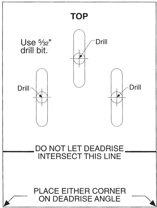
Remove and use for Transducer Installation
Contact Humminbird
Contact the Humminbird® Customer Resource Center in any of the following ways:
By Telephone
(Monday - Friday 8:00 a.m. to 4:30 p.m. Central Standard Time):
1-800-633-1468
By e-mail
(typically we respond to your e-mail within three business days):
custserv@johnsonoutdoors.com
For direct shipping, our address is:
Humminbird
Service Department
678 Humminbird Lane
Eufaula, AL 36027 USA

HUMMINBIRD®